20
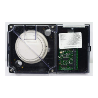
To properly remove and replace the detector/sensor to the base (see Figure 1):
1. Remove power from the Duct Detector/Sensor.
2. Loosen the four screws that secure the clear plastic cover to the housing base.
3. Insert a small blade screwdriver into the lock release slot in the base. Rotate
the detector/sensor counterclockwise to remove it from the base.
4. Remove dust cover from the replacement detector/sensor.
5. Insert the detector/sensor into the base and rotate until fully seated, continue
rotation until lock has been engaged.
6. Secure the clear plastic cover to the housing using the four screws (Torque
screws to 8-10 inch-pounds).
Note: An audible “snap” indicates proper contact engagement.
WARNING: System will not operate with dust cover in place.
Basic Unit Test
With power applied to the Duct Detector, introduce aerosol using the 553-673 Smoke
Detector Aerosol Tester into the Duct Detector through the test port holes (Figure 1).
Or, place the 553-810 Magnet Tester next to the test location on the clear Housing
Cover (Figure 16). Observe “ALARM” LED operation on the detector or the
“ALARM” LED on the interface PCB for DUCT Sensors. Restore normal operation
to detector by doing a system reset at the panel, or by momentarily removing power,
or by removing and replacing the detector head. Restore normal operation to sensor
by doing a system reset at the panel.
With the air handling unit turned on, and all filters and dampers in place, open one of
the test port holes (Figure 1) by removing one of the red covers marked “Test” on the
Duct Detector/Sensor. Measure the airspeed velocity inside the duct housing using
the Alnor Instrument Co. Air Velocity Meter (Model 8500) or equivalent (not
supplied).
Note: Refer to manufacturer instructions when performing this test.
Insert the probe in the test opening and measure the airspeed directly in front of the
sampling tube. Airspeed measured at this point should be 200 fpm or greater.
Airspeed measured at the inlet is typically 40% – 60% of the actual airspeed in the
duct housing. Any deviation from the recommended installation rules described
previously can cause this measurement to be unreliable.
If the airspeed measurement is less than 200 fpm, then a direct airspeed measurement
should be taken inside the duct. Airspeed inside the duct should be between 300 fpm
and 4000 fpm (91 to 1220m/min) for proper operation of the smoke detector/sensor.
Airspeed below 200 fpm measured inside of the duct detector/sensor may indicate a
sampling or exhaust tube obstructed by debris. Tubes should be inspected and
cleaned as required.
IMPORTANT: Make sure the test port covers are replaced after testing.
Continued on next page
Installation, Continued
Detector/Sensor Replacement
DC Operation Detector
Testing
Periodic Air Test
Technical Manuals Online! - http://www.tech-man.com