17
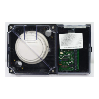
Figure 12. Template Positioning
Inlet Tube Selection
4. Inlet tubes should be selected and cut to length as specified in Table 3.
After trimming the inlet tube opposite the slot, tap rubber plug (supplied)
into the trimmed end. See Figure 13.
TUBE SUPPORT HOLE ONLY FOR
DUCTS MORE THAN 3 FEET WIDE
INLET TUBE HOLES
FACE UPSTREAM
OF AIR FLOW
EXHAUST TUBE
DO NOT INSERT RUBBER PLUG
FOR DUCT WIDTHS
3 FEET TO 95 INCHES
FOR DUCT WIDTHS
12 INCHES TO 3 FEET
INLET TUBE HOLES
FACE UPSTREAM
OF AIR FLOW
CUT EXHAUST TUBE TO 1/2 OF
DUCT WIDTH WHEN WIDTH
IS LESS THAN 24"
EXHAUST TUBE
DO NOT INSERT RUBBER PLUG
INSERT RUBBER PLUG
EXPECTED
AIR FLOW
DIRECTION
AIR FLOW
DIRECTION
12"
THIS END OF
INLET TUBE
Figure 13. Inlet Tube Orientation (Mounting Position 2 – See Figure 18)
EXHAUST TUBE
INLET
TUBE
RUBBER
PLUG
INLET TUBE HOLES FACE
UPSTREAM OF AIR FLOW
Figure 14. Inlet Tube Installation
Continued on next page
Installation, Continued
Duct Detector/Sensor
Installation, (continued)
HORIZONTAL DUCTS OVER 13" HIGH
OR
AIR FLOW
DIRECTION
OR
AIR FLOW
DIRECTION
HORIZONTAL DUCTS UNDER 13" HIGH
OR
AIR FLOW
DIRECTION
VERTICAL
DUCTS
NEVER MOUNT AT AN ANGLE
WITH RESPECT TO AIR FLOW
NO
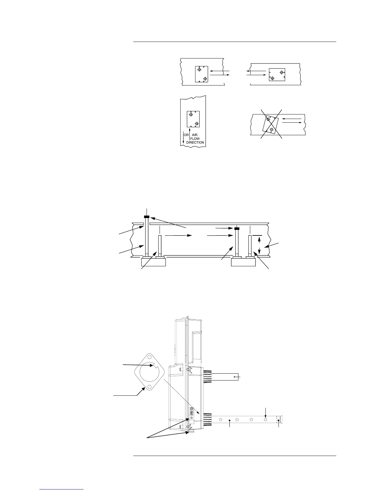
INLET TUBE RETAINER
BRACKET
TAB
SEE NOTE 1
Notes:
1. The tab on the inlet tube retainer bracket indicates the
inlet hole side of the pipe.
2. The inlet tube must be installed through the hole in the
housing corner next to the smoke port/air flow test holes.
SEE NOTE 2
Technical Manuals Online! - http://www.tech-man.com