page 6 579-1169 Rev E
4100-3109 IDNet 2, 4100-3110 IDNet 2+2 and 4100-3111 IDNet Loop card Installation Instructions
Wiring Overview
Each IDNet output from the IDNet 2 or IDNet Loop cards can be wired as a either an isolated Class A circuit or as two isolated Class B circuits.
Class A wiring provides an alternate communication path that allows communication to all devices to be maintained when a single open circuit
fault occurs. Class A wiring requires two wires to be routed from the IDNet 2 Primary Terminals (B+, B-) to each device, and then back to the IDNet
Secondary Terminals (A+, A-). Wiring is in/out, “T” tapping is not allowed.
Class B wiring allows “T” tapping. IDNet wiring is inherently supervised due to individual device level communications. End-of-line resistors are not
required.
Wiring Parameters
Table 2 identifies the card wiring parameters that must be considered when installing these cards.
Table 2: Card Wiring Parameters
Wiring Capacitance Parameters
Parameter Value
Maximum Supported Channel Capacitance; Total of all four Isolated
Outputs.
The sum of line-to-line capacitance, plus the capacitance of either line-to-shield
(if shield is present) = 0.6 μF (600 nF).
Capacitance between IDNet SLC wiring (between wires of the same
polarity; plus to plus, minus to minus).
1 μF maximum (this is for multiple IDNet loops).
Wiring Distance Limits (see note below).
Class B Wiring, Total Channel Wiring Parameters,
Including T-Taps
Class A Wiring, Total Channel Wiring
Parameters
Channel Loading
Up to 125 devices 126 to 250 devices Up to 125 devices 126 to 250 devices
Total Loop Resistance 50 Ω maximum 35 Ω maximum 50 Ω maximum 35 Ω maximum
18 AWG (0.82 mm2) 4000 ft (1219 m) per run,
12,500 ft (3810 m) total
2500 ft (762 m) per run,
10,000 ft (3048 m) total
4000 ft (1219 m) per loop,
12,500 ft (3810 m) total
2500 ft (762 m) per loop,
10,000 ft (3048 m) total
16 AWG (1.31 mm2)
14 AWG (2.08 mm2)
12 AWG (3.31mm2)
5000 ft (1524 m) per run,
12,500 ft (3810 m) total
2500 ft (762 m) per run,
10,000 ft (3048 m) total
5000 ft (1524 m) per loop,
12,500 ft (3810 m) total
2500 ft (762 m) per loop,
10,000 ft (3048 m) total
Note: Maximum wiring distance is determined by either reaching the maximum resistance, the maximum capacitance, or the stated maximum dis-
tance, whichever occurs first. Class A maximum distances are to the farthest device on the loop from either “B” or “A” terminals. For Class B wiring, the
maximum distance to the farthest device is limited to the stated Class A wiring distances.
Note: External wiring must be shielded (for lightning suppression) and 2081-9044 Overvoltage Protectors
must be installed at building exit and entrance locations.
Capacitance: Each protector adds 0.006 μF across the connected line.
Resistance: Each protector adds 3 Ω per line of series resistance; both IDNet lines are protected; 6 Ω per
protector will be added to total loop resistance.
Maximum distance of a single protected wiring run is 3270 ft (1 km).
Wiring Considerations using 2081-9044
Overvoltage Protectors.
(2081-9044 is UL listed to Standard
1459, Standard for Telephone
Equipment).
Refer to document number 574-832: 2081-9044 Overvoltage Protector Installation Instructions for additional
information.
Class A Wiring
To wire the Loop terminals as a Class A circuit:
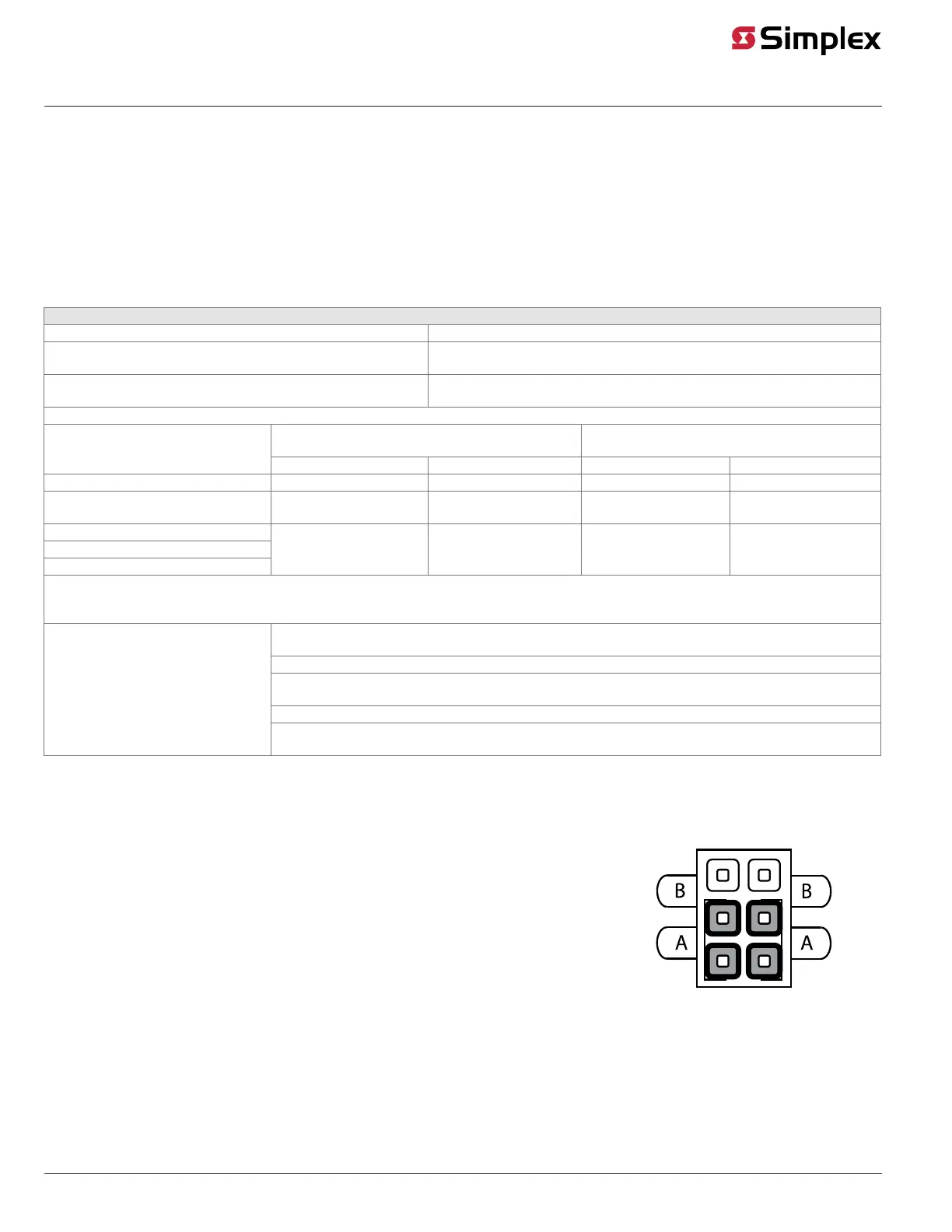
1. Set the jumper assigned to the loop to the “A” position, as shown in Figure 6.
- Loop A= Jumper P1 on the IDNet 2 card
- Loop B= Jumper P2 on the IDNet 2 card
- Loop C= Jumper P1 on the first IDNet Loop cards
- Loop D= Jumper P1 on the second IDNet Loop card
2. Shielded wire is not recommended. If shielded wires are present, cut and tape off the shield to
prevent it from coming in contact with other components. Metallic continuity of the shield must be
maintained and insulated throughout the entire length of the cable.
3. Route the wiring from the Primary Terminals (B+, B-) to the corresponding inputs on the first device.
4. Route wiring from the first device to the next as in/out. See Figure 7. Repeat for each device.
5. Route the wiring from the last device to the panel.
6. Connect the wiring to the corresponding Secondary Terminals (A+, A-).
Figure 6: Class A Jumper Setting
 Loading...