page 8 579-1169 Rev E
4100-3109 IDNet 2, 4100-3110 IDNet 2+2 and 4100-3111 IDNet Loop card Installation Instructions
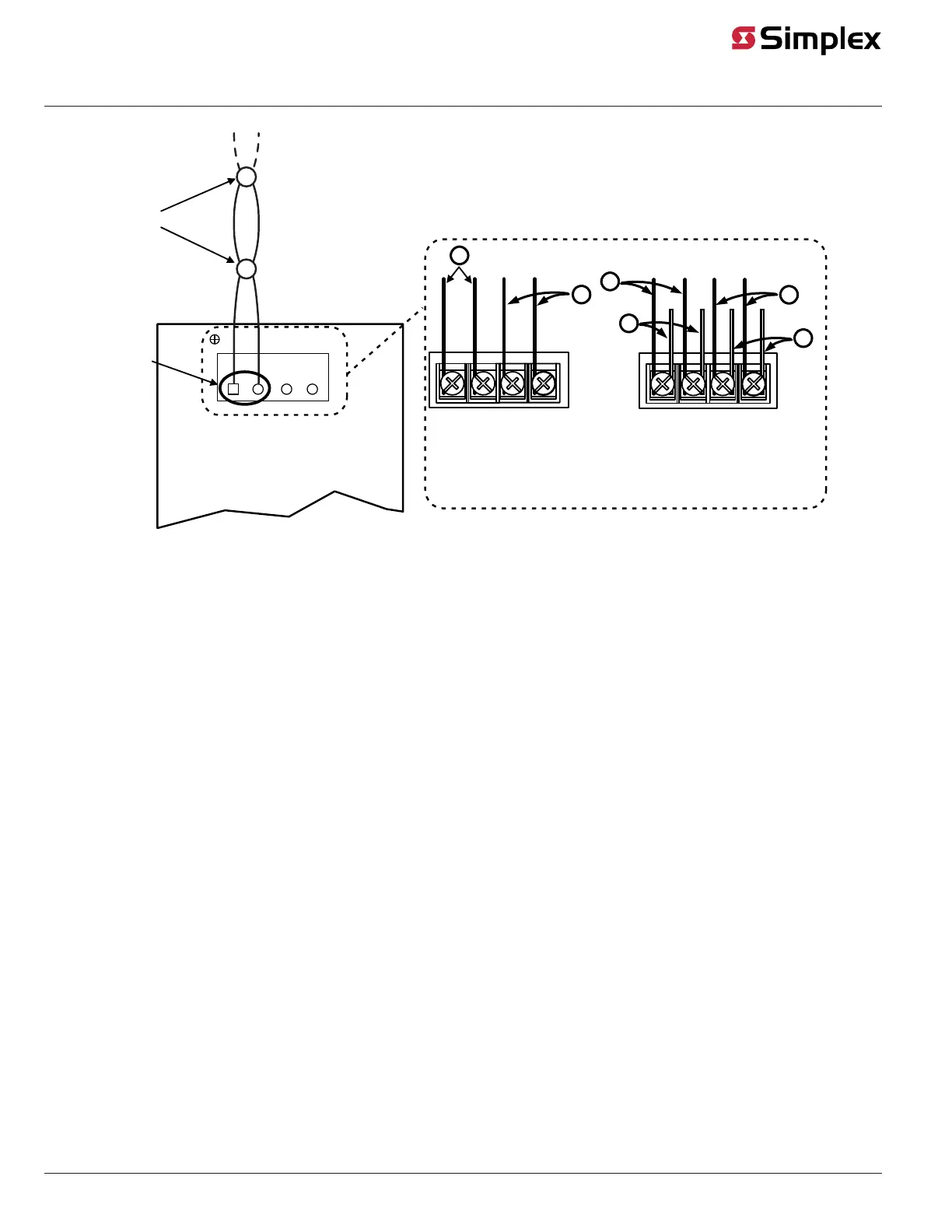
B+
TB1
IDNet CIRCUIT A
1
B- A+ A-
Devices
B+, B-
Terminals
2
1
4
3
Note: For Class B wiring only, up to 4 parallel wiring “T”
taps may be made at the output terminal blocks
2
1
Different Circuit Configurations
B+ B- A+ A-
2 Circuit Configuration
B+ B- A+ A-
4 Circuit Configuration
Figure 9: IDNet Loop Class B Wiring
Class B wiring Notes:
1. If no remote isolators or isolator bases are on the loops, device addressing can be assigned without concern for sequence.
2. If remote isolators or isolator bases are on the loops, the required addressing approach is to start at the output and assign each successive
isolator a higher address than the isolator it proceeds. For Class B wiring only, the “A” output and “B” output per loop are connected together
in parallel for wiring convenience.