page 7 579-1169 Rev E
4100-3109 IDNet 2, 4100-3110 IDNet 2+2 and 4100-3111 IDNet Loop card Installation Instructions
+
1
2
1 2 1 2
IDNet 2 Card
Devices
18 to 12 AWG
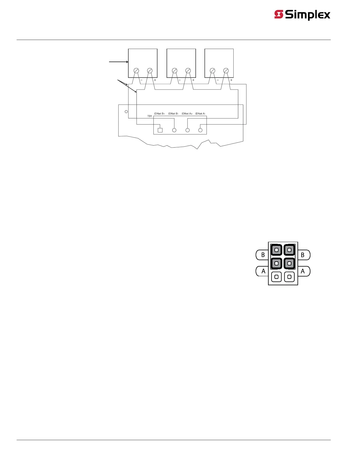
Figure 7: IDNet Loop Class A Wiring
Class A wiring notes:
1. If no remote isolators or isolator bases are on the loops, device addressing can be assigned without concern for sequence.
2. If remote isolators or isolator bases are on the loops, the required addressing approach is to start from the “B” side and assign each
successive isolator a higher address than the isolator it proceeds.
Class B Wiring
When wiring the loop for Class B circuits, both the B+, B- and A+, A- terminals are available for parallel connections. Within the IDNet circuitry, A+ is
connected to B+, and A- is connected to B- so circuits can stem from either one. Additionally, two wires can be connected to each screw terminal.
To wire the Loop terminals as a Class B circuit:
1. Set the jumper assigned to the loop to the “B” position, as shown in Figure 8.
- Loop 1 = Jumper P1 on the IDNet 2 card
- Loop 2 = Jumper P2 on the IDNet 2 card
- Loop 3 = Jumper P1 on the left IDNet Loop card
- Loop 4 = Jumper P1 on the right IDNet Loop card
2. Route wiring from the Primary Terminals (B+, B-) to the corresponding inputs on the first device.
It is possible to add up to 4 circuits per IDNet loop on the terminal block when using Class B wiring. See
Figure 9 for the diagram.
3. Route wiring from the first device to the next as in/out as shown in Figure 9. Repeat for each device.
4. Shielded wire is not recommended. If shielded wires are present, cut and tape off the shield at each
end (in the panel and at the last device in each run) to prevent it from coming in contact with other
components. Metallic continuity of the shield must be maintained and insulated throughout the entire
length of the cable.
Figure 8: Class B Jumper Setting