11
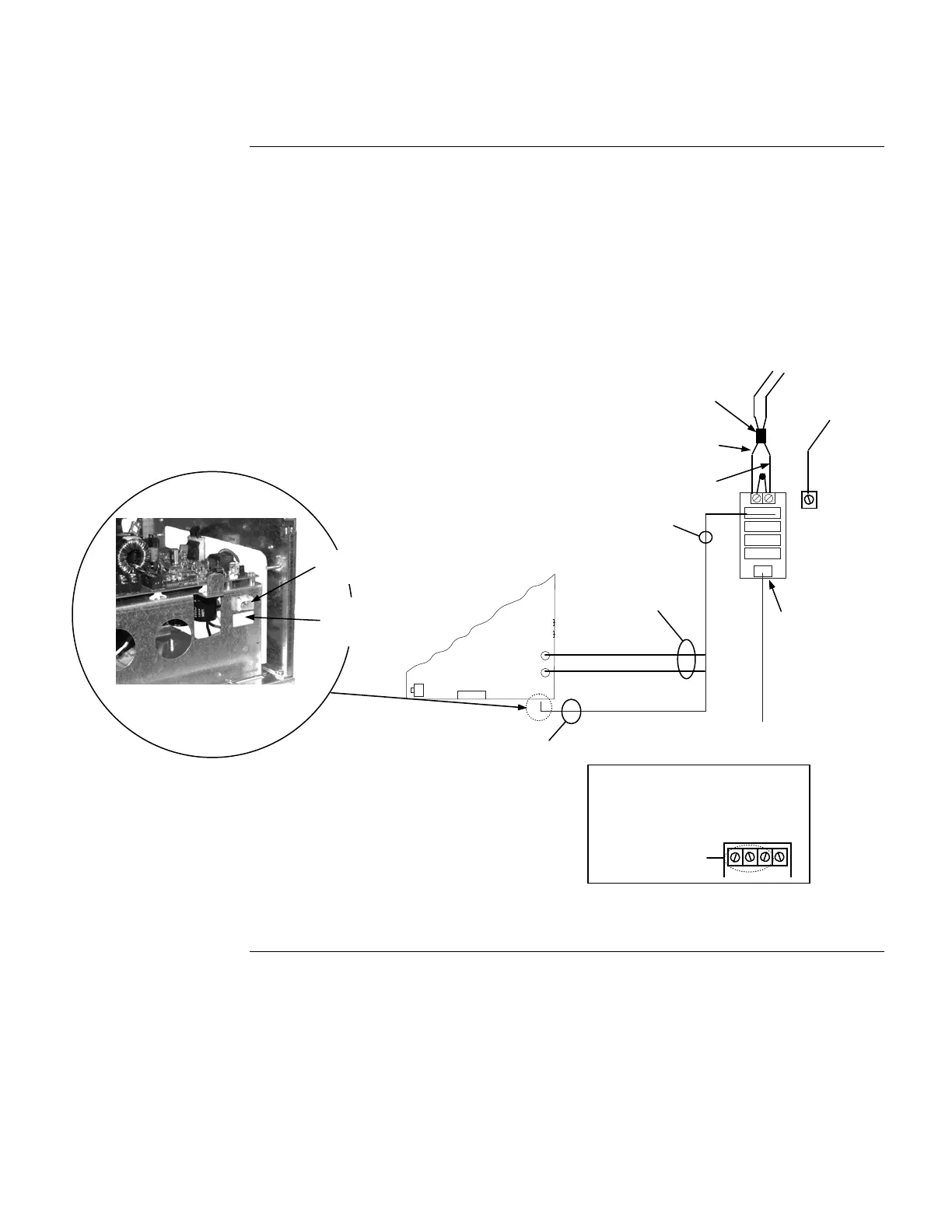
4. Connect the PDM to the SPS or RPS using Harness 734-012 (734-013 for 220/230/240VAC
versions).
Feed Red and Black wires through the side rail to the front of the SPS or RPS to
prevent wire damage when the front panel is inserted.
Connect the separate Red and Black wires (with Yellow female terminations) to plugs
P5 (Black) and P4 (Red) on the SPS or RPS.
Connect the White and Black wires, which terminate together in a White snap-on
connector, to the bulkhead connector at the bottom of the SPS or RPS assembly,
as shown below.
P1
P2
P3
P4
P5
Figure 5. SPS Assembly Connector
Internal Wiring,
Continued
Power Distribution
Module Connections
SPS
120 V TO TRANSFORMER
THROUGH BULKHEAD
CONNECTOR
SPS ASSEMBLY
(CPU bay assembly
shown)
RED WIRE
BLACK WIRE
P4
P5
Bulkhead connector
BATTERY
HARNESS
FUSED AT 15 A
HARNESS 734-015
TO 24 V BATTERY
HARNESS
(734-012)
(734-013)*
GROUND
BACK BOX
GROUND
SCREW
*220/230/240VAC PART NUMBERS
APPEAR IN ITALICS.
220 VAC
230 VAC
240 VAC
NEUT
50/60 Hz
2 A
566-248
220/230/240VAC
PDM TERMINAL
BLOCK
Second bulkhead
connector here in
220/230/240VAC
versions
120 V
NEUTRAL
120 VAC
60 Hz, 4 A
FERRITE
BEAD
PDM
(566-246)
(or 566-248;
see below)*