8
The SPS and RPS have jumper ports (see Figure 1) for the IDNet shield connection, Earth ground
monitoring, and for city or relay module trouble activation. The SPS and RPS also require an
address setting via DIP switch SW1. This section describes each setting.
P1: Earth Fault Monitor jumper. Position 1-2 enables Earth fault monitoring; Position 2-3
disables Earth fault monitoring. Set for [1-2] in all systems except those with TrueAlert
Power Supply (TPS, 4100-5120/5121/5122) modules. Set for [2-3] in systems with TPS.
P2: (SPS only). IDNet Shield Connection Jumper. If the SPS IDNet outputs are being used,
you may change P2 to configure the IDNet shield connection. Position 1-2 connects the
shield to 0 V (default); Position 2-3 connects the shield to Earth ground.
P3 City/Relay Hardwired Trouble Jumper. Position 1-2 removes trouble monitoring on Relay
3 (default) of the 4100-6033 Alarm Relay Card; Position 2-3 activates the
4100-6031/6032 City Cards or the 4100-6033 Alarm Relay Card when the system
microprocessor fails. Always use Position 2-3 for 4100-6031/6032 City Cards.
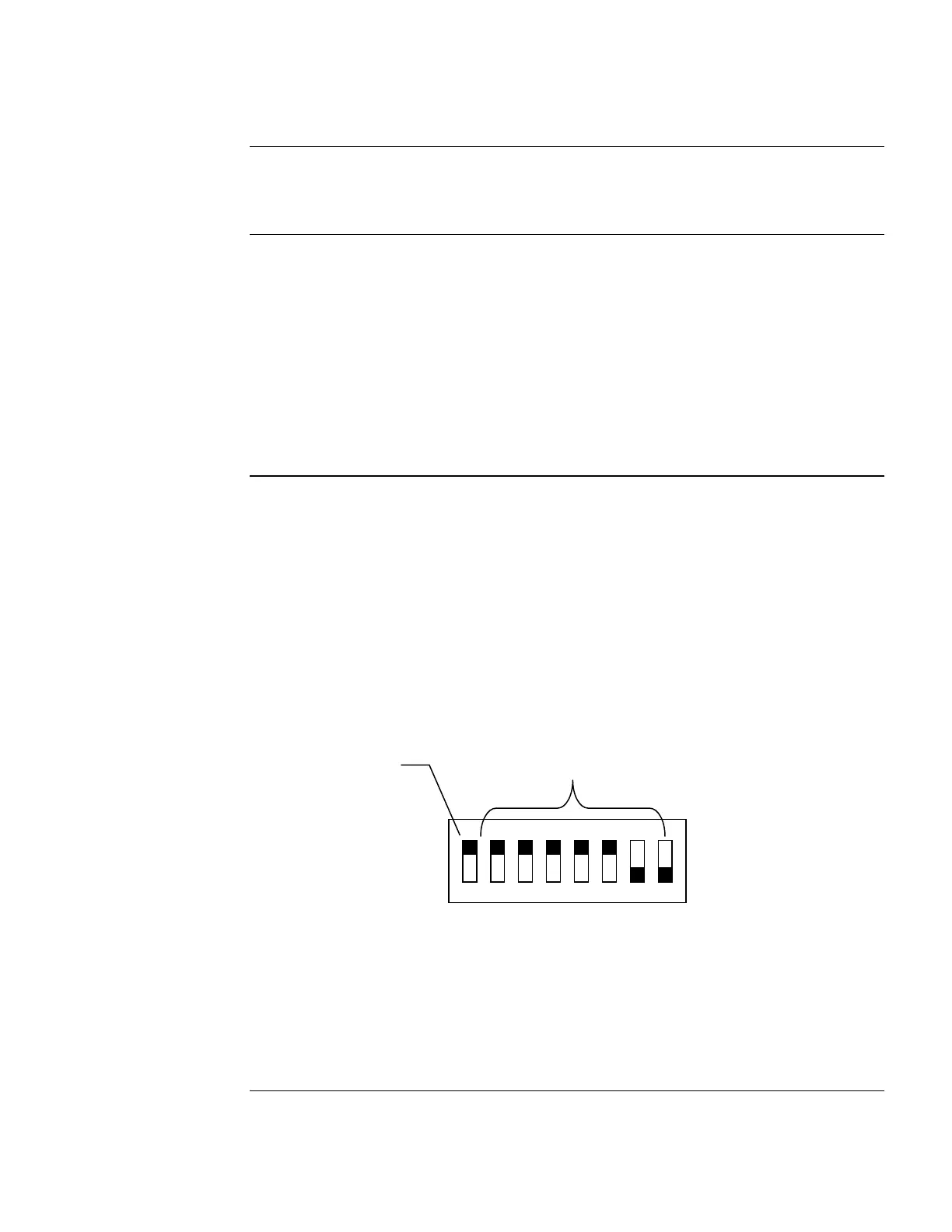
The SPS or RPS device address is set via DIP switch SW1, which is a bank of eight switches. From
left to right (see below) these switches are designated as SW1-1 through SW1-8. The function of
these switches is as follows:
SW1-1: This switch sets the baud rate for the internal 4100 communications line running
between the card and the 4100 CPU. Set this switch to ON.
SW1-2 through SW1-8: These switches set the card’s address within the 4100 FACP.
Refer to Table 4 for a complete list of the switch settings for all of the possible card
addresses.
Note: You must set these switches to the value assigned to the card by the Programmer.
FigureTag FD9-246-01
1
8
7
6
5
4
3
2
Figure 3. DIP Switch SW1
The model 4100-5112 (SPS) and 4100-5126 (RPS) are required in jurisdictions, such as Canada,
where depleted battery conditions are required, by local code, to result in power-down of the unit
until AC power is restored. The system must also be programmed for depleted battery cutout, for
each power supply.
Continued on next page
Configuring the SPS and RPS
Overview
Jumper Settings
Setting the Address
ON
OFF
DIP Switches SW1-2 through
SW1-8 set the Card Address.
Figure shows an Address of 3.
4100 Comm. Baud Rate.
Switch (SW1-1)
Must Be Set to ON