24
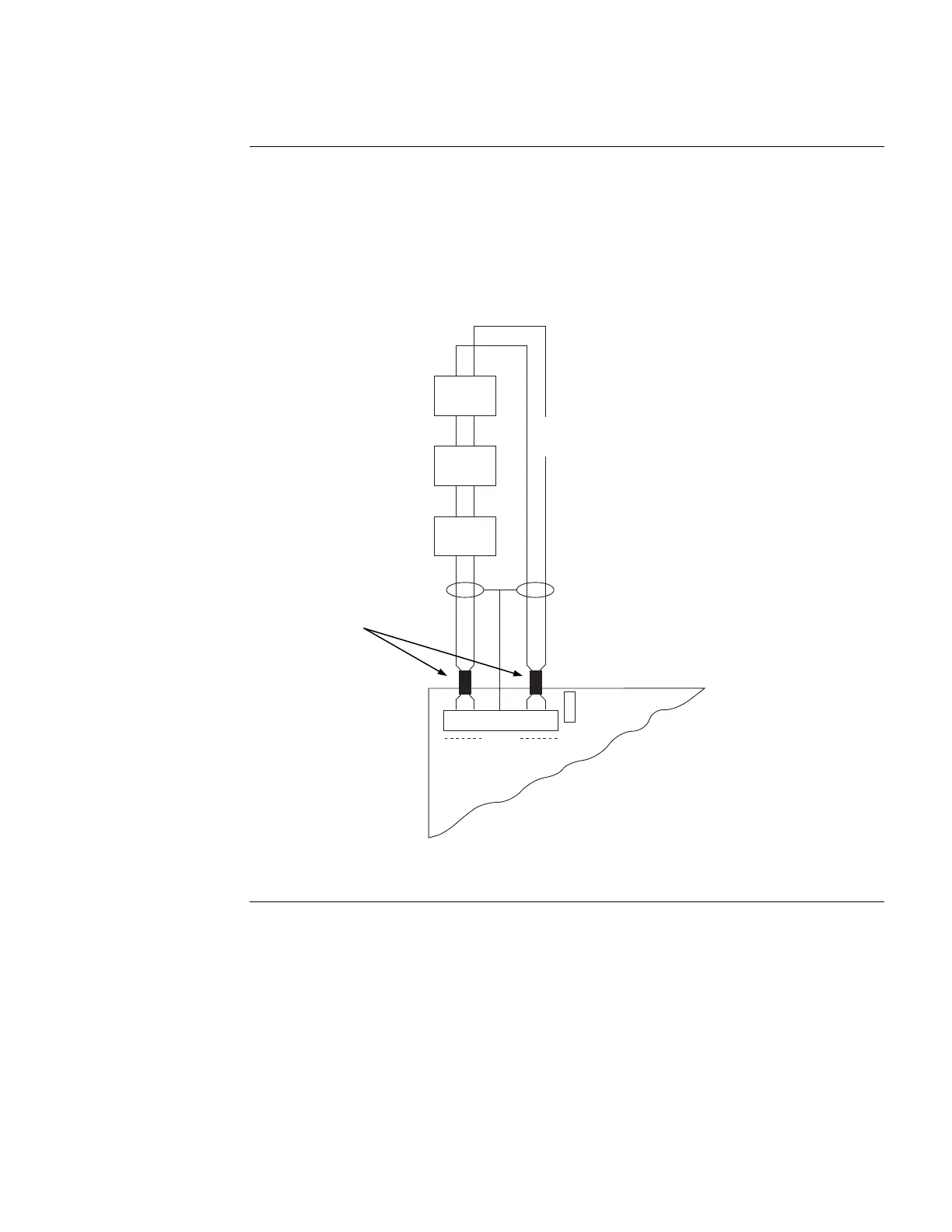
To connect the SPS to IDNet appliances using Class A wiring, read the following instructions.
1. Route wire (between 12 [3.309 mm
2
] and 18 AWG [0.8231 mm
2
]) from the B+, B-, and
SHIELD outputs on TB1 of the SPS to the appropriate inputs on a peripheral IDNet
appliance.
2. Route wire from the first IDNet appliance to the next one. Repeat for each appliance.
3. Route wire from the last IDNet appliance to the A+ and A- inputs on TB1 of the SPS.
B+ B- SHLD
IDNet
A+
P1
3
2
1
A-
IDNet LOOP
(CLASS A / STYLE G)
IDNet
DEVICE
IDNet
DEVICE
IDNet
DEVICE
Figure 10. Class A Wiring
Continued on next page
IDNet Field Wiring (SPS only),
Continued
Class A Wiring
IDNet LOOP
(CLASS A/STYLE 6)
Ferrite beads
required