28
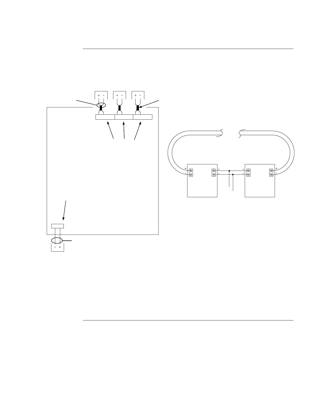
The figure below shows how the SPS or RPS is wired for auxiliary power at any given terminal.
B+
0V 24V
AUX POWER
B- A+A- B+ B- A+ A- B+ B- A+ A-
AUXILIARY
POWER
AUXILIARY
POWER
AUXILIARY
POWER
AUXILIARY
POWER
Figure 13. Auxiliary Power Wiring
Auxiliary Power Wiring,
Continued
Wiring
Note: To program relay contacts, refer to the ES Panel Programmer’s Manual (574-849).
Devices
Primary Return
TB1 TB2
24V
0V
TB1 TB2
To SPS
or RPS
Class A aux power wiring requires the
use of 4090-9117 IDNet Power
Isolators, as shown above.
4090-9117
ISOLATOR
4090-9117
ISOLATOR
Class A wiring requires a 4090-9117 Power Isolator is used.
CE compliant systems require ferrite beads. Use Kit 4100-5129.
SPS or RPS
TB2
TB3
Dedicated auxiliary
power screw terminal
(configured in the
Programmer)
NAC points must be
reconfigured as
auxiliary power
output points in the
programmer
12 AWG (3.309 mm
) to
18 AWG (0.8231 mm
2
)
12 AWG (3.309 mm
) to
18 AWG (0.8231 mm
2
Ferrite bead
required for
CE compliance.
Use Kit 4100-5129.