4
The figure below details the SPS. The only difference in physical appearance between the SPS and
the RPS is that the SPS contains IDNet screw terminals.
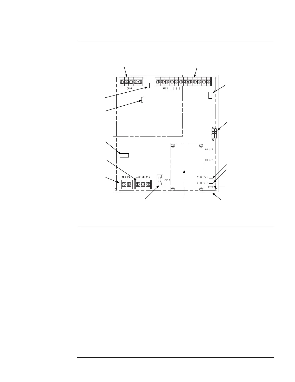
Figure 1. The System Power Supply (SPS)
The SPS and RPS have the following LEDs:
LED 1 (Yellow): Illuminates when NAC 1 is in Alarm or Trouble.
LED 2 (Yellow): Illuminates when NAC 2 is in Alarm or Trouble.
LED 3 (Yellow): Illuminates when NAC 3 is in Alarm or Trouble.
LED 4 (Yellow): Illuminates to indicate a communications loss with the system CPU; normally
OFF. If this LED is blinking, try re-loading the software to FLASH.
LED 5 (Yellow): Indicates IDNet status.
Slow blink: Class A or open circuit trouble.
Fast blink: Short circuit trouble.
ON steady: No devices detected/ channel failure.
Normally OFF.
LED 6 (Yellow): Indicates power supply status.
Single blink: Positive Earth fault.
Double blink: Negative Earth fault.
Triple blink: Battery trouble.
Quadruple blink: Charger trouble.
ON steady: Overcurrent fault.
Normally OFF.
LED 7 (Green): Illuminates when the power supply is powered from the AC line. OFF when the
power supply is de-energized, or when it is using battery backup power
Continued on next page
Introduction to the SPS and RPS,
Continued
Overview
NAC Terminal Block (TB2)
City/Relay Card
Mounting Area
(City card mounts to SPS Only)
City Card
Connector (P7)
Auxiliary Relay
Terminal Block
(TB4)
Auxiliary Power
Terminal Block
(TB3)
AC Connector
(Under Board)
Battery Connectors:
P4
P5
Power/Comm to
CPU Motherboard
(P8)
IDNet Terminal Block (TB1; SPS only)
Device Address
Switch (SW1)
IDNet Shield
Jumper Port (P2)
City/Relay Card
Trouble Indication
Jumper (P3)
(SPS Only)
Earth Fault
Monitor Jumper (P1)
Power/Comm to
P1 of PDI (P6)