7
Ground Speed Control
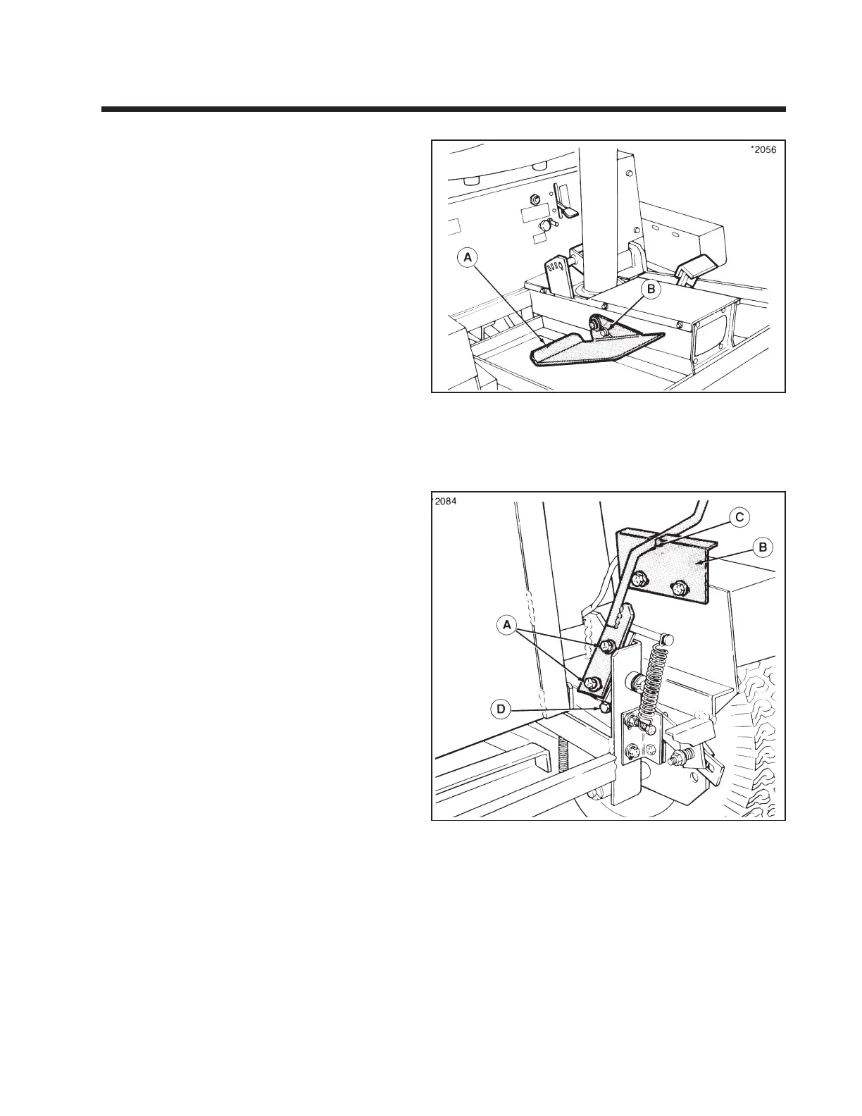
The position and angle of the foot pedal (A, figure
1-3) can be adjusted by loosening taptite screw (B)
and moving pedal in slot. This adjustment should
not affect rider speed or neutral adjustment.
Lever-Steer Adjustments
Control Levers
The control levers have slotted holes for mounting
and can be positioned for the most comfortable
operating position. When in neutral, the handles
should be opposite each other.
To adjust the angle of lever, loosen capscrew
(A, figure 1-4). Adjust lever position and retighten
capscrew. Neutral gate brackets (B) must be adjusted
so that new position of lever will be aligned with
neutral gate (C) when rider is in neutral.
In the operating position, handles should have about
1/2" between them so they will not contact each
other with the weight of the operator’s hands on
handles. To adjust distance, loosen locknut and turn
adjusting bolt (D) in or out. Retighten nut after
adjustment.
After handle adjustment, check the neutral adjust-
ment to make sure there is no creep with levers in
neutral position. Readjust spring-centered lever
position. (Refer to following adjustments.)
Figure 1-3.
A. Foot Pedal
B. Adjustment Capscrew
Figure 1-4.
A. Capscrew
B. Brackets
C. Neutral Gate
D. Adjustment Bolt
Section 1. (Continued)
Commercial Front-Cut Rider with Dual Eaton Model 7 Hydrostatic