10
Wheel- & Lever-Steer
Forward Travel Stop
The adjustment bolt (A, figure 1-9) can be rotated to
limit the maximum output speed of each hydro
pump so that the rider will travel in a straight
direction at full forward ground speed. For hydro
output speed variation at less than full forward
position, refer to “Transmission Speed Variation
Adjustment”.
For double-chain reduction models, turn the bolt all
the way out. With ground speed control set to full
forward position, turn the bolt in until it contacts the
frame. Turn the bolt an additional 1/2 turn so that
internal hydro pump components are not used as the
forward travel stop.
For single-chain reduction models, adjust the bolt so
drive wheels are turning 130 rpm maximum.
The left or right adjustment bolt can be turned
inward an additional amount required to limit the
output speed of a faster hydro pump if there is
noticeable difference at maximum forward speed.
If unit is equipped with set collar (C, figure 1-9),
turning the adjustment bolt will affect the reverse
travel stop. (Some early model lever-steer units did
not require set collar.) Perform the “Reverse Travel
Stop Adjustment” to reposition the set collar if
forward travel stop is adjusted.
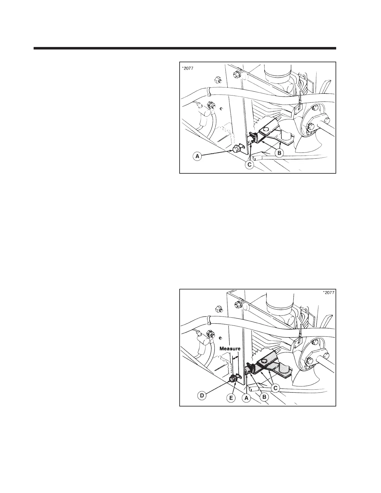
Reverse Travel Stop
The maximum reverse speed of each hydro pump is
controlled by the position of a set collar (A, figure 1-
10) that limits the travel of hydro input linkage (C).
Adjust the forward travel stop, if necessary, before
adjusting reverse travel stop.
The factory pre-set position of the set collar limits the
reverse speed of rider to 3.5 mph. If the set collar
position is changed due to adjusting the forward
travel stop or service work, set collar (A) should be
repositioned so that there is 1-1/4" (double-chain
reduction models) or 5/8" (single-chain drive
models) between flat washer (E) and frame bracket
with ground-speed control in the full reverse
position.
Figure 1-9.
A. Adjustment Bolt
B. Hydro Input Linkage
C. Set Collar
Figure 1-10.
A. Set Collar D. Capscrew
B. Setscrew E. Flat Washer
C. Hydro Input Linkage
Section 1. (Continued)
Commercial Front-Cut Rider with Dual Eaton Model 7 Hydrostatic