24
Install the Heat Shield
1. Install the heat shield as shown in Figure 49.
Position the shield 1/8” right of the “T” of “HOT”.
Install the Lift Linkage and Rear Hitch
Bracket
ELECTRIC LIFT MODELS
1. Remove the hair pin clip (A, Figure 50) and slide the
shaft assembly (C) out far enough to remove the lift
tube assembly.
2. Push the shaft assembly back through the lift support
far enough to mount the rear hitch bracket (A, Figure
53), washers (D), and hairpin clips (C).
3. Push the shaft assembly (D, Figure 50) back through
the lift support and reinstall the hair pin clip (A).
4. Install the lift lever extension (D, Figure 51) onto the
shaft assembly (C, Figure 50) and secure to the lift
arm assembly (E, Figure 50) with the clevis pin (B,
Figure 51) and hair pin clip (C, Figure 51).
5. Install the front lift rod(A, Figure 51) into the lift lever
extension (D) and secure with a hair pin clip.
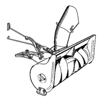
Figure 51. Electric Lift Models
A. Front Lift Rod
B. Clevis Pin
C. Hairpin Clip
D. Lift Lever Extension
Figure 49. Heat Shield Installation
A. Heat Shield C. Clip
B. Carriage Bolt D. Lockwasher, 1/4
1/4-20 x 7/8 E. Nut, 1/4-20
CAUTION
The heat shield shown in Figure 49, is supplied
with the hitch assembly and must be installed
before installing hitch assembly. Damage to
snowthrower could occur if heat shield is not
installed.
Remove heat shield when removing snowthrower
and hitch assembly.
E
D
A
C
B
Position shield 1/8"
from “T” on grille.
Figure 50. Electric Lift Assembly
A Hair Pin Clip D. Lift Support
B Lift Tube E. Lift Arm Assembly
C Shaft Assembly
C
D
B
A
E
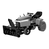
Landlord-Snowthrower Assembly
 Loading...