24
A
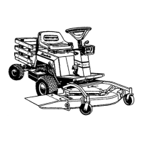
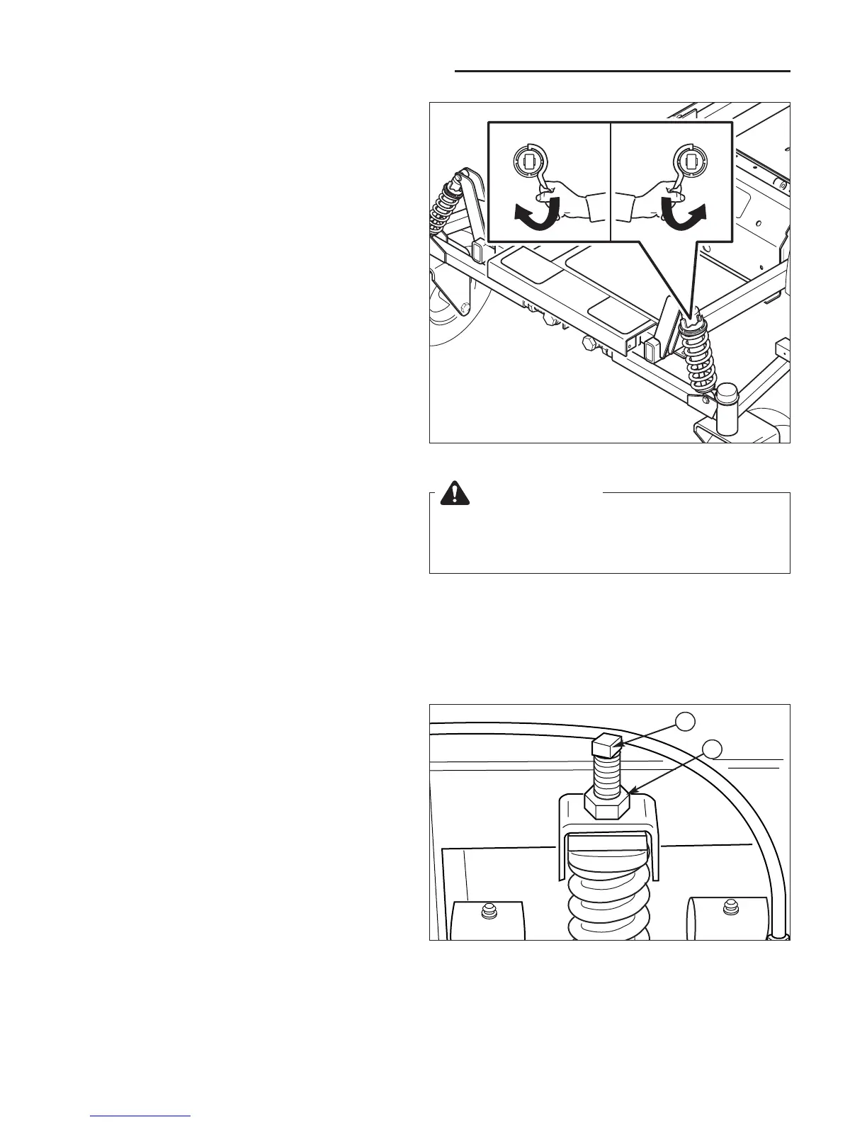
Figure 30. Suspension Height Adjustment
A. Height Adjustment Bolt
B. Jam Nut
B
FRONT SUSPENSION ADJUSTMENT
The shock assembly can be adjusted to vary the amount
of pre-load applied to the springs. This allows the opera-
tor to customize the ride according to operator’s weight
and/or operating conditions.
LESS PRE-LOAD:
• Light operator weight
• Softer, more cushioned ride
• Best for relatively flat terrain
MORE PRE-LOAD:
• Heavy operator weight
• Stiffer, more rigid ride
• Better handling and greater stability on hilly terrain
TO ADJUST THE SPRING PRE-LOAD:
1. Park machine on a flat, level surface. Disengage the
PTO, stop the engine and engage the parking brake.
2. See Figure 29. Using the supplied spanner wrench
(p/n 5022853), insert the tip of the wrench into the
notch in the pre-load adjuster. While holding the
wrench in place with one hand, turn CLOCKWISE to
increase the pre-load, turn COUNTER-CLOCKWISE
to decrease the pre-load. Make sure both shocks are
set to the same amount of pre-load.
NOTE: Spanner wrench is located behind the rear seat
cross member, on the left-hand side of the machine.
REAR SUSPENSION ADJUSTMENT
If the rider tilts either side-to-side or front-to-rear, this
adjustment will level the frame with the ground.
Although this adjustment may not be necessary, it may
be required if additional weight (ie. a grass catcher) is
added to the frame or a drive tire is replaced.
NOTE: Perform this adjustment on a hard, level surface
such as a concrete floor.
Measure the distance between the ground and the bot-
tom of the frame, behind the drive tires. This should
measure 9-3/4” (24,7 cm) for both sides for 25hp model;
10-1/4” (26 cm) for 27hp model. If it does not, loosen the
jam nut (B, Figure 30) and turn turn the height adjust-
ment bolt (A) COUNTER-CLOCKWISE to lower the cor-
responding side of the frame, and CLOCKWISE to raise
the frame. Tighten the jam nuts.