17
4.8 DC Voltage Measurement 0-2.5 ~ 0-250V Range
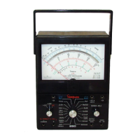
a. Set the function switch at +DC (Figure 4-1).
b. Plug the black test lead into the – COMMON jack and the red test lead into
the + jack.
c. Set the range switch at one of the five voltage range positions marked 2.5V,
10V, 25V, 50V or 250V.
NOTE: When in doubt as to the voltage present, always use the highest voltage
range as a protection to the Instrument. If the voltage is within a lower range, the
switch may be set for the lower range to obtain a more accurate reading. Be sure
power is off in the circuit being measured and all capacitors discharged.
d. Connect the black test lead to the negative side of the circuit being measured
and the red test lead to the positive side of the circuit.
e. Turn on the power in the circuit being measured.
f. Read the voltage on the black scale marked DC. For the 2.5V range, use the
0-250 figures and divide by 100. For the 10V, 50V, and 250V ranges, read the
figures directly. For the 25V range, use the 0-250 figures and divide by 10.
NOTE: Turn off power to the circuit and wait until the meter indicates zero before
disconnecting the test leads.
4.9 DC Voltage Measurement 0-500V Range
!
Be extremely careful when working with high voltage circuits. Do not
touch the Instrument or test leads while power is on in the circuit being
measured.
Before proceeding with the following steps, re-
view the Safety Precautions in 4.2.
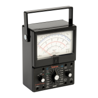
a. Set the function switch at +DC (Figure 4-
2).
b. Set the range switch at the 250V/500V/
1000V position.
c. Plug the black test lead into the – COM-
MON jack and the red test lead into the
500V jack.
d. Be sure power is off in the circuit being
measured and all capacitors discharged.
Connect the black test lead to the nega-
tive side of the circuit being measured and
the red test lead to the positive side of the
circuit.
e. Turn on power in circuit being measured.
f. Read the voltage using the 0-50 figures
on the black scale marked DC. Multiply
the reading by 10.
NOTE: Turn off power to the circuit and wait
until the meter indicates zero before
disconnecting the test leads.
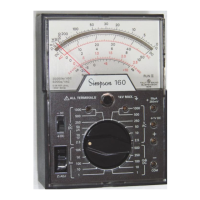
FIGURE 4-2. Jacks and Switch
Positions for Measuring DC Voltage,
0-500V Range
D.C
.
D.C
.
250 V.
500 V.
I000 V.
COMMON
-
- D.C.
+ D.C.
260
ALL TERMINALS 1 V MAX
500 V.
A.C. D.C.