27
R x 1
R x I0,000
+
COMMON
-
- D.C.
+ D.C.
O
HMS
OHMS
260
ALL TERMINALS 1 V MAX
R X I00
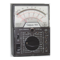
FIGURE 4-12. Jacks and Switch Positions for Measuring Resistance
5 OPERATOR MAINTENANCE
5.1 General
The following paragraphs in this section describe battery replacement, fuse re-
placement, and preventive maintenance procedures for the 260-8.
5.2 Inspection
The user is protected from electrical shock by the insulation of the 260 and its test
leads. Frequently examine them for any insulation damage such as cracks, cuts,
chips, burns or deterioration that ex-
pose internal metal parts or reduce
the spacing between such metal
parts and hand contact by the opera-
tor.
Make certain that the battery com-
partment cover is securely fastened
in place before the Instrument is
used.
Do not use an Instrument with a bro-
ken meter glass.
FIGURE 5-1. Battery and Fuse Com-
partment
Whenever the battery compartment
cover is removed for any reason,
check that the proper fuses are be-
ing used.
LAC DU FLAMBEAU, WI