62
Installation and Maintenance
Service Manual
Step Procedure
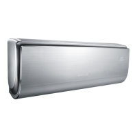
3.Remove panel
Open the front panel; separate the panel rotation shaft
from the groove xing the front panel and then removes
the front panel.
Note:
The display of some models is fixed on the panel;
unscrew the screws fixing the display on the panel
before removing the panel.
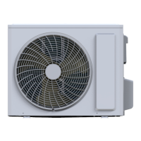
4.Remove electric box cover 2
Remove the screws on the electric box cover 2 to
remove the electric box cover 2.
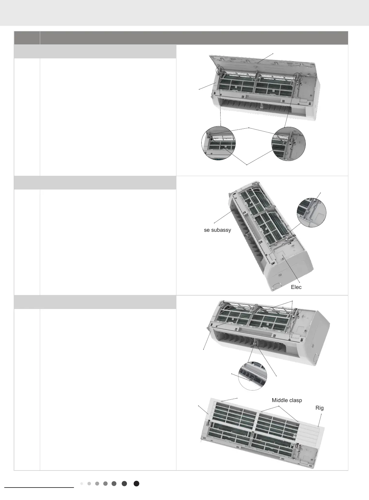
5.Remove front case sub-assy
a
b
Remove the screws xing front case.
Note:
(1) Open the screw caps before removing the screws
around the air outlet.
(2) The quantity of screws fixing the front case sub-
assy is different for different models.
Loosen the clasps at left, middle and right sides of front
case. Life the front case sub-assy upwards to remove
it.
Front case subassy
Electric box cover 2
Screw
Screw
Screw
Panel rotation
Groove
Panel
Front panel
Screw caps
Right clasp
Middle clasp
Left clasp
Front case sub-assy
Front case
sub-assy