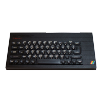
Sinclair ZX Spectrum Service Manual
Spectrum For Everyone https://spectrumforeveryone.com/
15
1.9 TAPE INTERFACE
When LOADing or SAVEing programs using a cassette recorder, the ULA transfers information between
the MIC and EAR sockets and the data bus, performing A/D and D/A conversions as required. Since the
LOAD and SAVE functions are mutually exclusive, a single pin on the ULA (i.e. pin 28) is used both for input
and output. Separate I/O read/write cycles to port address 254 configure the pin accordingly. During the
LOAD operation, the CPU executes successive I/O read cycles, reading the EAR input off data bus line 6.
When performing a SAVE operation, the CPU executes successive I/O write cycles, this time writing data
to the MIC output via data bus 3.
To ensure that I/O cycles are correctly implemented, the IOREQ line supplying the ULA is gated with
address line A0 via TR6. Thus, if any memory transactions occur where A0 is high (i.e. not port address
254) then the IOREQ input is forced high inhibiting any attempt to perform an I/O cycle.
1.10 LOUDSPEAKER (BEEP) OPERATION
It should be noted that while SAVEing the level of the MIC output is barely sufficient to drive the
loudspeaker via D9 and TR7 (D10). However, during the execution of a BEEP instruction the CPU writes
instead to port 254 on data bus 4. This effectively boosts the MIC output, driving the loudspeaker so that
the BEEP tone can be easily heard. During the execution of such an instruction the cassette recorder is not
running so there is no conflict at the MIC/EAR sockets.
1.11 POWER SUPPLIES
The on-board power supply unit requires a 9V unregulated supply from the external Sinclair ZX power
pack and derives the following internal supply rails:
• Regulated +5V for the IC logic circuits, the ULA and the UHF modulator.
• -5V and +12V for the standard 16k dynamic RAM.
• +12V for the colour modulator circuits.
The external power pack incorporates a mains transformer, full wave rectifier and capacitive smoothing.
A thermal fuse is fitted at the transformer input.
The on-board power supply unit incorporates a 7805 regulator, deriving the +5V power rail, and an
inverter stage TR4/TR5. The latter raises the level of the +9V unregulated supply to in excess of +12V. The
resultant square wave at the junction of TR4 collector and the inverter coil is subsequently rectified and
smoothed by D5/C44 producing the +12V output for the RAM. Additional smoothing, imparted by
R62/C45, produces the +12V supply for the TV circuits free from noise generated by the RAM, and is
available at the expansion port for use by peripherals. The +12V, +5V and -5V are also made available.

 Loading...