- 10 -
CZ sincro
DG83 D
1
2
3
4
5.0 MEASUREMENT OF INJECTION TIME
After connection to battery, the unit is set for reading injection time. Injection
time can be measured at progressive preset engine speeds. This possibility
allows to check the correct relationship between the most important parameters
of petrol and LPG fuelled engines.
Select different functions through key
V
.
A blinking zero shows a lack of electrical signal.
5.1 Perform the measurement by picking up the injection signal through
the TL 220 cable connected to the AD16 adapter (fig. 11) or to the
AD33A needle (fig. 13). Fig. 11 shows an engine with DIS system, in
this case select 1spark per revolution through key
2
4
.
Select 2 sparks per revolution where necessary, press key
V
until
P1P1
P1P1
P1
is displayed. Press key D twice,
P3P3
P3P3
P3
and
1S 1S
1S 1S
1S
will be displayed (fig. 6 in
the yellow sheet). By pressing C+ /–,
2S2S
2S2S
2S
will be displayed.
Press key D once and proceed with reading.
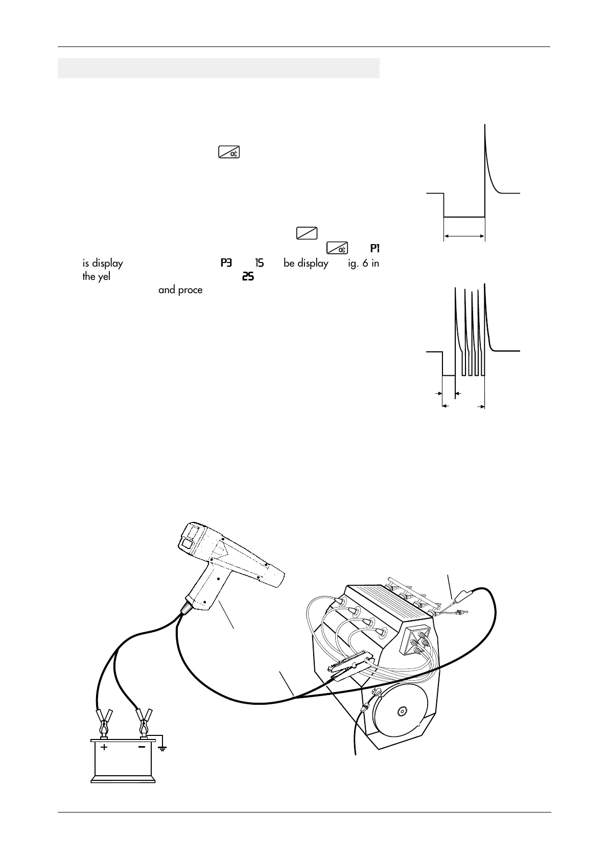
5.2 Fig. 10 shows the signals of two types of injectors:
Type A with an internal resistance of 16 Ω, driven from the beginning
to the end of injection by a current without intermittances.
Type B with an internal resistance of 2 Ω, driven by an initial opening
current and a series of maintenance current pulses during ope-
ning.
The unit automatically recognizes the type and gives the total injection
time measurement.
In timed injection systems (ex. IAW Marelli) the check can be carried
out by connecting the TL220 cable in sequence to each injector.
Fig. 11
INJECTION TIME MEASUREMENT
Black
AD16 adapter
(optional)
Red
12V
Fig. 10
A
B
Beginning End
INJECTOR OPENING
Initial
opening
TL 220
cable
Beginning End
Key D