- 8 -
CZ sincro
DG83 D
V
2
4
RESET
STROBOTESTER DG 83-D
min.
V=
Volt/Duty Cycle
4.0 CHECKING IGNITION SYSTEM PERFORMANCE
Checking the ignition coil’s charging time allows to diagnose some system’s
operating faults. See NOTE on page 9. A blinking zero appears in case the
signal is not present.
4.1 In points systems, measurement is carried out in percentage or degrees.
Connect the unit to the negative pole of the ignition coil (see Fig. 8).
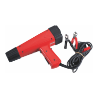
Press and release key . Dwell measurements in milliseconds will
be displayed. Keep key pressed until
P SS P SS
P SS P SS
P SS
is displayed.
Press keys C + /– until
PP PP
PP PP
PP
(percentage) or
GG GG
GG GG
GG
(degrees) is displayed
(Fig. 6). Press and release key D,
P 1 P 1
P 1 P 1
P 1
will appear.
For percentage measurements select the cylinder number through keys
C + /– (Fig.7). For single cylinder engines or coil per plug systems
select 1 cylinder and confirm by pressing key D. Press key
2
4
to
select 1 spark per revolution on DIS systems. For 2 sparks selection
follow the instructions in chapt.3.
Press key D to proceed with measurements.
4.2 In systems with electronic ignition module, possible lacks of command
signal from the reluctor sensor, Hall sensor or from the ECU, can be
due to faults in connection or in the module. Carry out checks described
in par. 6.3.
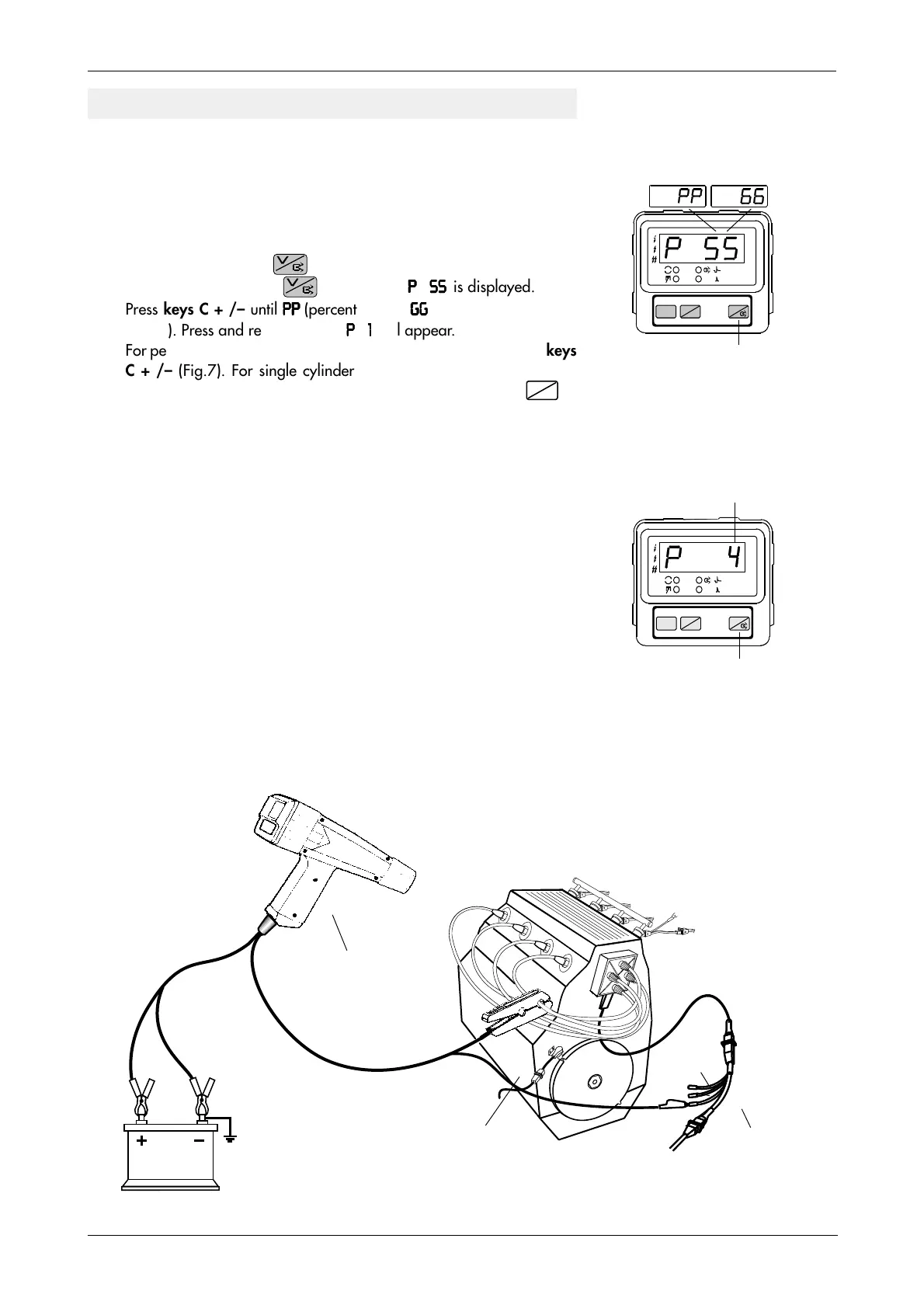
4.3 Fig. 8 shows a connection of a DIS system. By connecting the TL220
cable through the AD33A needle, or the AD17 adapter (optional) to
the A or B primary wire and the clamp to one of the cylinders 1-4 or
2-3, the strobotester will check the performance of ignition modules.
Module C in 6-cylinder engines (Fig. 9) can be checked by connecting
the TL 220 cable to the terminal of the AD18 adapter and the inductive
clamp to the spark cable of one of the cylinders 5-6.
Fig. 8
CHECKING CHARGING TIME OF DIS IGNITION COILS OR DWELL
12 V
AD17
A
B
+ 15
TL 220 cable
Key D
Fig. 7
Fig. 6
Black
Red
Setting the number
of cylinders
Setting percentage
or degrees
1
2
3
4
V
2
4
RESET
STROBOTESTER DG 83-D
min.
V=