mod. DG83-D SINCRO August, 08, 2009
Setting percentage
or degrees
After connection to battery, the unit makes an autotest then it
will set automatically for measuring RPM on engines with 1 spark
per 2 revolutions (4 stroke 4 cylinder engines).
To measure ignition advance press key D and make the TDC
marks to correspond by pressing keys C + / – .
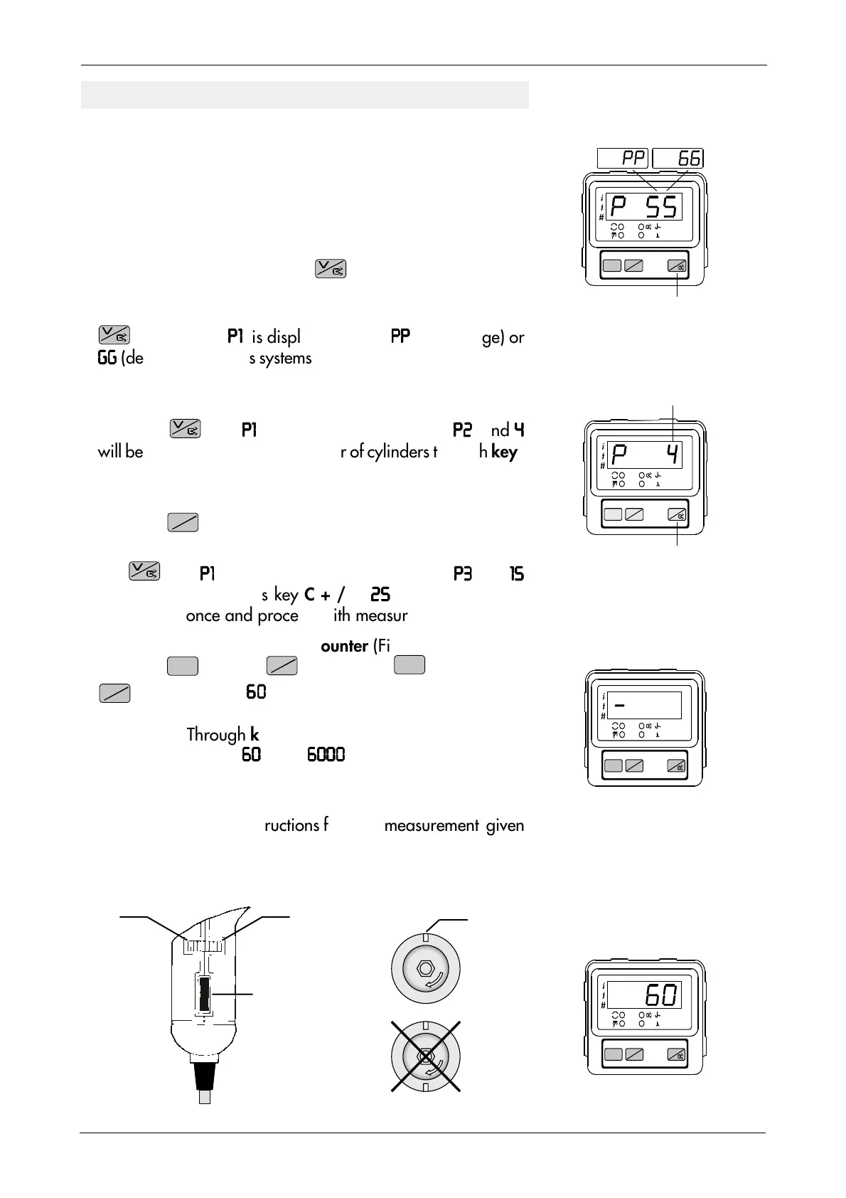
1.Setting the Duty cycle
With key D released, press key for a while, the duty cycle
(or Dwell) in mS will appear on display. To measure Dwell
angle in Percentage or Degrees (Fig. 21), keep key
pressed until
P1P1
P1P1
P1
is displayed. Select
PPPP
PPPP
PP
(percentage) or
GGGG
GGGG
GG
(degrees) for points systems through keys C + /– . Confirm
by pressing key D three times and proceed with measurement.
2.Setting the number of cylinders (Fig. 22).
Press key until
P1P1
P1P1
P1
is displayed. Press key D ;
P2 P2
P2 P2
P2
and
44
44
4
will be displayed. Select the number of cylinders through keys
C +/–. Press key D twice and proceed to measure.
3.Setting one or two sparks per revolution (Fig. 23).
Press key
2
4
to select one spark per revolution (DIS systems
or 2 stroke engines). To select 2 sparks per revolution, press
key until
P1P1
P1P1
P1
is displayed. Press key D twice,
P3 P3
P3 P3
P3
and
1S1S
1S1S
1S
will be displayed. Press key C + / –,
2S2S
2S2S
2S
will be displayed.
Press key D once and proceed with measurement.
4.Setting the stroboscopic RPM counter (Fig. 24).
Press key
RESET
then key
2
4
. Release key
RESET
and keep key
2
4
pressed until
6060
6060
60
is displayed. The unit will blink
automatically. Trace a white line on the rotating part with a
white chalk. Through keys C + /– it is possible to increase or
decrease RPM from
6060
6060
60
up to
60006000
60006000
6000
.
RPM reading has to be made when the white reference line
traced (fig. 25A) is still.
NOTE Follow detailed instructions for each measurement given
in the relevant chapters.
Fig. 21
SETTING FOR MEASUREMENTS
DG83-D – KEYS FUNCTION
Reference line
Setting the number of
sparks per revolution
Fig. 23
Setting the number
of cylinders
Fig. 22
V
2
4
RESET
STROBOTESTER DG 83-D
min.
V=
V
2
4
RESET
STROBOTESTER DG 83-D
min.
V=
V
2
4
RESET
STROBOTESTER DG 83-D
min.
V=
D
Flash
Memory
Confirmation
C-
to decrease
advance
Fig. 25
B
A
Reference
Right
Wrong
(double
frequency)
Fig. 24
Fig. 26
C+
to increase
advance
Setting the stroboscopic
RPM counter
V
2
4
RESET
STROBOTESTER DG 83-D
min.
V=