- 12 -
CZ sincro
DG83 D
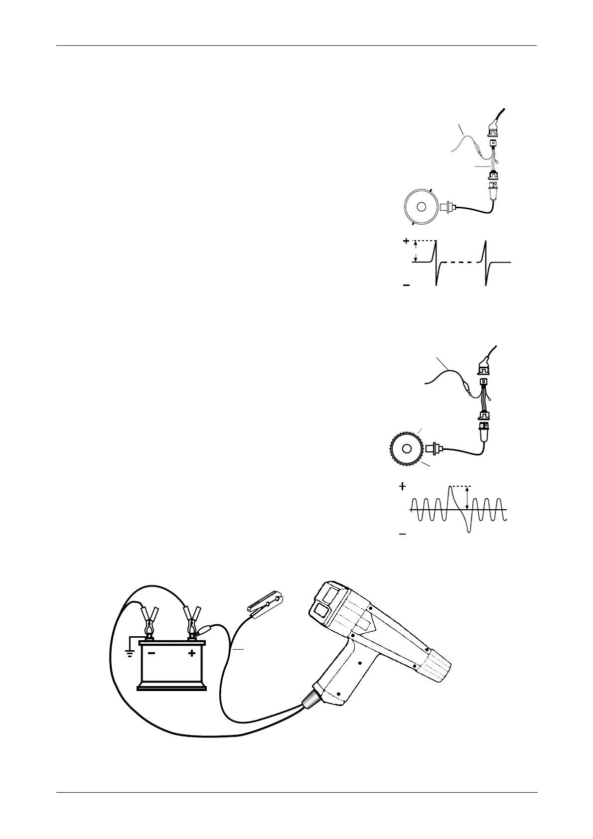
6.3 Peak voltage of reluctance sensors
Peak voltage of reluctance sensors can be found on some types of
ignition modules. Disconnect it from the module and put one end to
ground, connect the other end to the TL 220 cable.
Peak voltage at cranking is about 4 peak Volts and Dwell of 3 ÷ 4
milliseconds. Voltage can decrease if the distance beween the shaft
teeth and the sensor increases.
6.6 Hall effect sensors
Some transistorized ignition modules are driven by a HALL effect sensor
that supplies a square wave voltage to the module, with a fixed or
variable dwell according to the engine speed.
There are three contacts on the sensor’s connector: ground, power supply
and 0 (output signal). For a complete test, check the peak output voltage
and the signal’s Dwell on contact 0 of the connector. Voltage is usually
5 V. In some systems it is 12 V.
6.7 Voltage drop at cranking
Connect first the Black and then the Red power clip, then connect the
TL 220 cable to the car battery positive pole (Fig. 17). Press key D,
crank the engine and release the key one second after engine dragging.
If the key is pressed too late or after the engine is cranked, voltage
drop at cranking will not be displayed. Voltages below 9,6 Volts can
cause fault codes in the ECU. Check the performance of battery, cranking
motor and alternator’s charging system.
6.8 Battery charging voltage
Bring the engine to about 3000 RPM for a few seconds, battery voltage
will increase to 14.0 Volts. If voltage does not increase, check the voltage
regulator and the alternator.
PEAK VOLTAGE OF
INDUCTIVE SENSORS
Fig. 15
Fig. 17
VOLTAGE DROP AT CRANKING AND BATTERY CHARGING VOLTAGE
TL220 Cable
12 V
Fig. 16
TL 220 cable
Flywheel
Crankshaft
position
peak V
Black
Red
Pulley
AD9-AD10 Marelli-
Bosch adapters
peak V
TL 220 cable