EA180 Series Servo Drive Users Manual
41
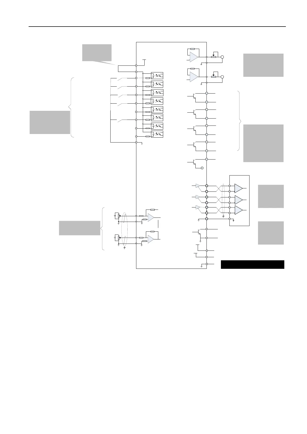
3.8.3 Torque control mode
8
23
37
38
9
24
39
10
DO1
DO1-
DO2
DO2-
DO3
DO3-
DO4
DO4-
State output
Encoder frequency
division pulse
output-differential
PE
PA+
PA-
PB+
PB-
PZ+
PZ-
28
13
12
27
26
GND
14
11
35
14
Upper
device
GND
Encoder phase Z
open collector
output
GND
OCZ
GND
AO1
Analog 1
output
Analog 2
output
15
29
30
29
GND
GND
AI2
AI1
EA180
servo drive
1. See P6 group function code
description for DO terminal
functions;
2. Refer to Section 3.4.6 for DO
terminal wiring method;
3. User-provided: DC5V ~ 24V
Max allowable voltage: DC30V
Max allowable current:
DC50mA
Servo ready
Brake output
Torque
comparison
Fault output
Refer to Section
3.4.9 for
frequency
division output
circuit
Refer to Section
3.4.9 for Z signal
output circuit
Refer to Section 3.4.7 for
analog input circuit
Refer to Section 3.6 for AO
output wiring
PE
+24V
+24V power
supply
25
COM+
21
DI1
5
DI2
20
4
DI3
19
3
18
2
DI4
DI5
DI6
DI7
17
DI8
ALM-RST
N-OT
TDIR-SEL
S-ON
P-OT
COM
State input
1. See P6 group function
code description for
functions of DI terminals
2. See Section 3.4.5 for DI
terminal wiring method
Standard connection
uses the internal
+24V power supply
by default
7
Servo enabled
Alarm reset clear
No positive drive
No negative drive
Torque command
direction selection
S-RDY
BK
Tcmp
ALM
A
GND
AO1
A
Speed command
Analog torque
Signal input: ± 10V
Input impedance: 9kΩ
Analog torque limiting
Signal input: ± 10V
Input impedance: 9kΩ
C N 1 terminal
41
COM
DO5
Internal shorting
+5V
+5V
GND
6
29
Internal +5V power supply, with max
allowable current of 50mA
+10V
+10V
44
Internal +10V power supply, with max
allowable current 20mA (Note)
(Note)
Note: DO5/+10V is not supported by
all models
Figure 3-26 Torque control mode standard wiring diagram
3.9 Notes for control circuit wiring
The control circuit cable and the power cable must be separated at a minimum distance of
30cm.
If the control circuit cable is short and needs to be extended, please ensure that the shield is
reliably connected to ensure reliable shielding and grounding.
The + 24V of servo drive is referenced by COM, and + 5V/+ 10V is referenced by GND. The
load should not exceed the maximum allowable current, otherwise the drive will not work
properly.
Try to use the shortest command input and encoder cables.
Please use cables above 1.5 mm
2
for grounding.
Single ground point is required.
 Loading...
