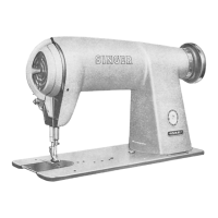
SPECIFICATIONS
The following
gouge
distances
should be of help to
adjusters
of
these
machines
. . .
•
Height
of
presser
foot
above
throat
plate:
Machines
451K41
and
451K45,
9/32
inch.
Machine
451K145,
5/16
inch.
•
Needle
bar
stroke:
Machines
451K41
and451K45,
1-9/64
Inches.
Machine
451K145,
1-5/16
inches.
• Rise of
needle
bar
from lowest position to position
where
hook point
reaches
centre
of
needle
(LOOP
LIFT):
Machines
451K41
and
451K45,
.085
inch.
Machine
451K145,
.100
inch.
• Height of
feed
dog
above
throat
plate, .0415 to
.0445
inch.
• Clearance
between
retaining portion of bobbin
case
holder
position
finger
and
bobbin
case
holder,
.020
to
.024
inch.
•
Clearance
between
bobbin
case
holder
and
side
edges
of bobbin
case
position finger,
.020
to .024 inch.
Certain conditions of sewing may necessitate slight
variations
from
these
settings.
BALL
BEARING
AND
NEEDLE
BEARING
NOTES
There
are
three ball bearings
and
three needle
bearings in each of these machines. With reasonable,
care these bearings should enjoy a long
and
trouble-
free
life.
Follow
oiling instructions given on pages 4, 5 and 6,
carefully.
When handling bearings outside of machine, care
should
be
token
to see that no foreign matter gets
into
these
bearings.
Ball
bearings
on
forward
end
of
arm
shaft
and
rear
end
of hook driving
shaft
are
forced fitted into
their correct position at factory and should not be
removed except for replacement.
When replacing ball bearings, make certain that
shielded side is always out
(on
less
protected
side)
and that they form a tight fit on their respective shafts.
Ball
bearing on machine pulley is also a forced fit.
The three needle bearings should receive some care
as ball
bearings
and
should not be removed from their
respective housings except for replacement. Needle
bearings should be replaced by pressing on numbered
end
of
outside
shell.
Any pressure on unnumbered end may distort shell
and
cramp
bearings.
After installation, core should be taken to see
that
needle
bearings
roll
freely
intheir
respective
housings.
PRELIMINARY
INSPECTION
Before
any
unnecessary
time
and
effort
is
spent
making major adjustments or installations, check fol
lowing conditions
of
machine
performance.
1.
Sample
of
work
currently
produced
on this ma
chine.
2.
Needle
and
thread
in use. (See
pages
6
and
7.)
3. Threading. (See
pages
7
and
8.)
4.
Speed
of
machine.
(See
page
3.)
5. Lubrication condition. (See
pages
4, 5
and
6.)
Before checking
and
adjusting
a
machine
that
has
been
idle
for
some
time,
check
for
hardened
oil
or
grease
between
moving
parts.
Dip
machine
in Varsol
or a
similar
cleaning
compound
and
remove
all
hard
ened
lubricant. Then oil machine completely
as
in
structed on
pages
4, 5
and
6.
After
a
machine
has
had
considerable
use,
check
for
worn
out
parts,
loose-fitting
shaft,
eccentrics, forks
and
links,
bent
needle
bar,
presser
bar
and
needle,
damaged
hook,
throat
plate, presser foot
and
feed
dog. Replace all
parts
showing
wear
with
SINGER*
parts
for
top-performance.
TO
TIME
THE
MACHINE
Timing the machine consists of first adjusting
the
radial
position of
sewing
hook with
relation
to
move
ment of needle
bar
and
needle thread take-up, so
that loop of thread cast out by needle will be correctly
token by point of hook
at
proper time for desired
stitch formation. Check-spring
and
feed
are
then timed
to
synchronize
their
motions
with
needle
and
hook
movements.
Timing instructions below
and
on
pages
13 through
16 should be followed in
exact
order
given for efficient
results.
1.
TO
TIME THE ROTARY TAKE-UP
AND
ARM
SHAFT
WITH
HOOK
DRIVING
SHAFT
Take-up
and
other
ports on these shafts
are
cor
rectly timed
when
their locating screws
are
in
shaft
splines
provided
for
them.
These
locating screws have a cone-shaped point and
are
the first screws to
appear
when shafts
are
re
volved
in
their
normal
direction
of
rotation.
Arm
shaft
and
hook driving
shaft
(with their com
ponents)
ore
in time with each other, for
average
sewing, when timing mark
E2,
Fig.
30,
page
13, on
take-up is in line with mark
F2,
Fig.
30 on face plate,
at
same
time that mark G2, Fig. 31,
page
13, is in line
with timing mark H2,
Fig.
31 on feed lifting connection.
To
adjust
for
average
sewing conditions, loosen
the
two pulley screws A2, Fig. 31; align timing marks E2
and
F2,
Fig.
30 and turn shaft
B2,
Fig.
31 as required
to align arrow G2 with mark H2, Fig. 31.
Securely
tighten
screws
A2.
12