THE
HOOK
DRIVING
SHAFT
REMOVAL
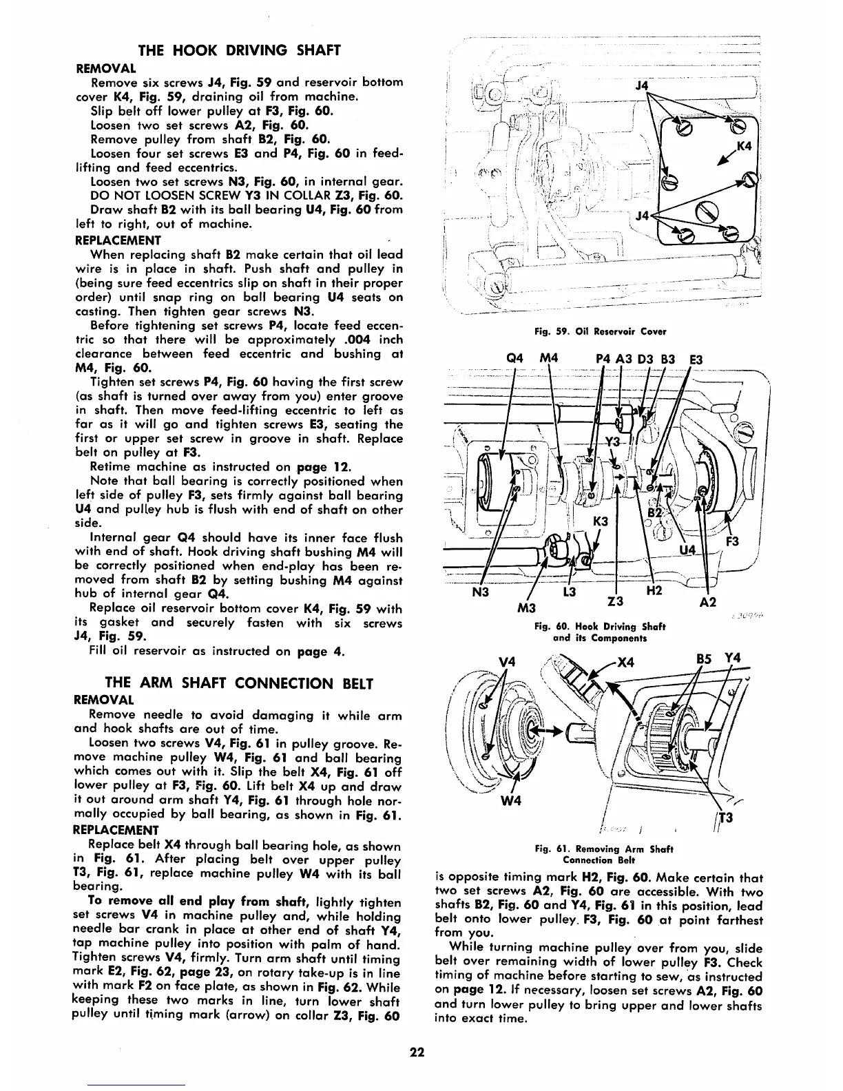
Remove six
screws
J4,
Fig.
59
and
reservoir
bottom
cover
K4, Fig.
59,
draining
oil
from
machine.
Slip
belt
off
lower
pulley
at
F3, Fig.
60.
Loosen
two
set
screws
A2,
Fig.
60.
Remove pulley from
shaft
B2, Fig.
60.
Loosen
four
set
screws
E3
and
P4, Fig.
60
in
feed-
lifting
and
feed
eccentrics.
Loosen
two
set
screws
N3, Fig.
60,
in
internal
gear.
DO NOT LOOSEN SCREW Y3 IN COLLAR
Z3,
Fig.
60.
Draw
shaft
B2
with
its
ball
bearing
U4, Fig.
60
from
left to
right,
out
of
machine.
REPLACEMENT
When
replacing
shaft
B2
make
certain
that
oil
lead
wire
is in
place
in
shaft.
Push
shaft
and
pulley
in
(being
sure
feed
eccentrics slip on
shaft
in
their
proper
order) until
snap
ring on ball
bearing
U4
seats
on
casting.
Then
tighten
gear
screws
N3.
Before
tightening
set
screws
P4,
locate
feed
eccen
tric so
that
there
will be
approximately
.004
inch
clearance
between
feed
eccentric
and
bushing
at
M4,
Fig.
60.
Tighten
set
screws
P4, Fig.
60
having
the
first
screw
(as
shaft
is
turned
over
away
from you)
enter
groove
in
shaft.
Then
move
feed-lifting
eccentric
to
left
as
far
as
it will
go
and
tighten
screws
E3,
seating
the
first or
upper
set
screw
in
groove
in
shaft.
Replace
belt
on pulley
at
F3.
Retime
machine
as
instructed on
page
12.
Note
that
ball
bearing
is correctly positioned
when
left side of pulley F3, sets firmly
against
ball
bearing
U4
and
pulley
hub
is flush
with
end
of
shaft
on
other
side.
Internal
gear
Q4
should
hove
its
inner
face
flush
with
end
of
shaft.
Hook driving
shaft
bushing
M4 will
be correctly positioned when end-ploy has been re
moved from
shaft
B2 by setting bushing M4
against
hub
of
internal
gear
Q4.
Replace oil reservoir bottom cover K4, Fig. 59 with
its
gasket
and
securely fasten with six screws
J4,
Fig.
59.
Fill
oil reservoir as instructed on
page
4.
THE
ARM
SHAFT
CONNECTION
BELT
REMOVAL
Remove
needle
to
ovoid
damaging
it while
arm
and
hook
shafts
are
out
of
time.
Loosen
two screws V4, Fig. 61 in pulley groove. Re
move machine pulley W4, Fig. 61 and ball bearing
which comes out with it. Slip the belt X4, Fig. 61 off
lower pulley at
F3,
Fig. 60.
Lift
belt X4 up and draw
it out
around
arm
shaft
Y4, Fig. 61 through hole nor
mally occupied by boll bearing, as shown in
Fig.
61.
REPLACEMENT
Replace belt X4 through boll bearing hole, as shown
in
Fig.
61. After placing belt over upper pulley
13, Fig.
61,
replace machine pulley W4 with its ball
bearing.
To
remove all end ploy from shaft, lightly tighten
set screws V4 in machine pulley
and,
while holding
needle
bar
crank In place at other end of shaft Y4,
tap machine pulley into position with palm of hand.
Tighten
screws
V4,
firmly.
Turn
arm shaft
until
timing
mark
E2,
Fig.
62, page 23, on rotary take-up is in line
with mark
F2
on face plate, as shown in
Fig.
62. While
keeping these two marks in line, turn lower shaft
pulley
until
timing
mark
(arrow)
on collar
Z3,
Fig.
60
22
Fig.
59.
Oil
Reservoir
Cover
Q4
M4
P4
A3
D3 B3 E3
Fig. 60. Hook Driving
Shaft
and
its Components
B5
Y4
Fig. 61.
Removing
Arm
Shaft
Connection
Belt
is
opposite
timing
mark
H2, Fig.
60.
Make
certain
that
two
set
screws
A2,
Fig.
60
ore
accessible.
With
two
shafts B2,
Fig.
60 and
Y4,
Fig. 61 in this position, lead
belt onto lower pulley. F3, Fig. 60 at point farthest
from you.
While turning machine pulley over from you, slide
belt over remaining width of lower pulley
F3.
Check
timing of machine
before
starting
to sew,
as
instructed
on
page
12. If necessary, loosen set screws A2, Fig. 60
and turn lower pulley to bring upper
and
lower shafts
into
exact
time.