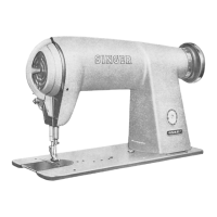
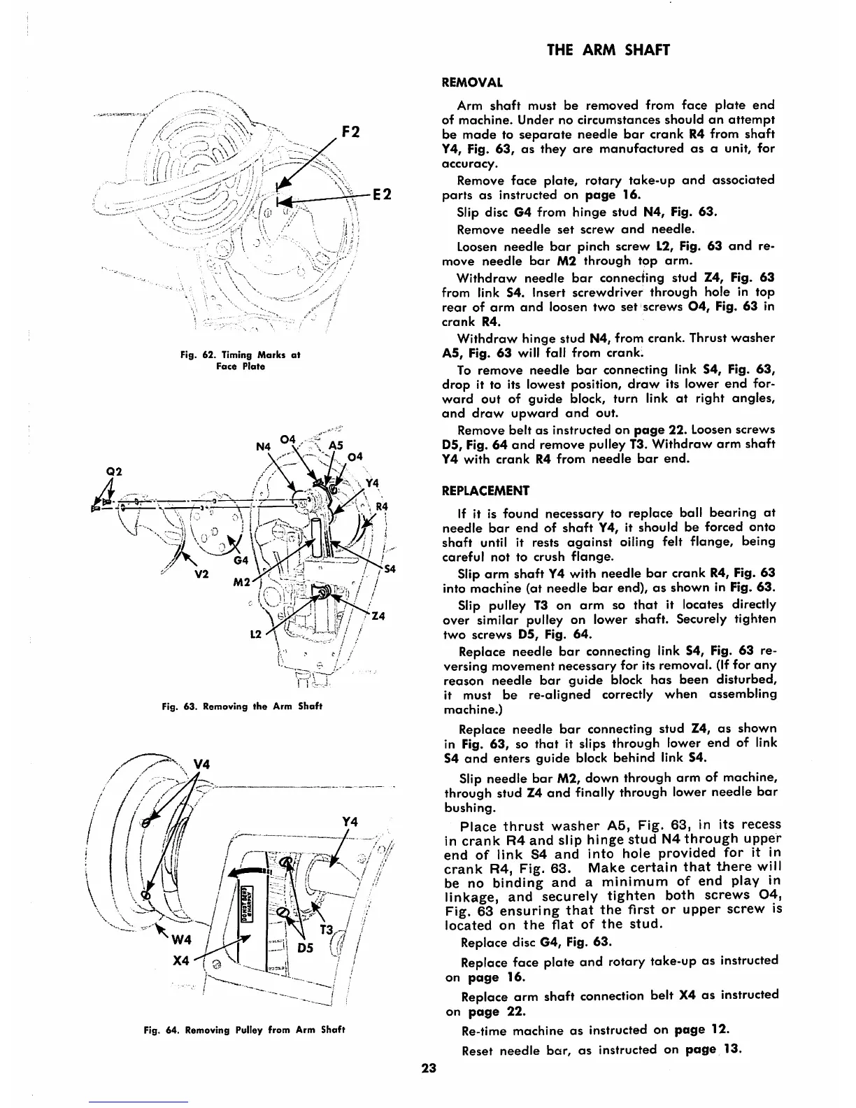
Fig. 62. Timing
Marks
at
Face
Plate
iC3«l
Fig. 63. Removing
the
Arm
Shaft
W4
/
Fig. 64. Removing Pulley from Arm Shaft
THE
ARM
SHAFT
REMOVAL
Arm
shaft
must
be
removed
from
face
plate
end
of
machine.
Under
no
circumstances
should
an
attempt
be
made
to
separate
needle
bar
crank R4 from
shaft
Y4, Fig.
63,
as they
are
manufactured
as
a unit, for
accuracy.
Remove face plate, rotary take-up
and
associated
parts
as
instructed on
page
16.
Slip disc G4 from
hinge
stud N4, Fig. 63.
Remove
needle
set
screw
and
needle.
Loosen needle
bar
pinch screw 12, Fig. 63
and
re
move
needle
bar
M2
through
top
arm.
Withdraw
needle
bar
connecting
stud
Z4, Fig.
63
from link 54. Insert
screwdriver
through
hole
in
top
rear
of
arm
and
loosen
two
set
screws
04,
Fig,
63
in
crank
R4.
Withdraw
hinge
stud
N4,
from
crank.
Thrust
washer
AS, Fig. 63 will fall from
crank.
To
remove
needle
bar
connecting
link
54,
Fig.
63,
drop it to its lowest position,
draw
its lower end for
ward
out
of
gurde
Islock,
turn
link
at
right
angles,
and
draw
upward
and
out.
Remove
belt
as instructed on
page
22. Loosen screws
D5, Fig. 64
and
remove pulley T3. Withdraw
arm
shaft
Y4
with
crank
R4
from
needle
bar
end.
REPLACEMENT
If it is found necessary to replace ball bearing at
needle
bar
end
of
shaft
Y4, it
should
be
forced
onto
shaft
until it rests
against
oiling felt
flange,
being
careful
not
to
crush
flange.
Slip arm shaft Y4 with needle
bar
crank R4, Fig. 63
into
machine
(at
needle
bar
end),
as
shown
in Fig.
63.
Slip pulley
T3
on arm so that it locates directly
over similar pulley on lower shaft. Securely tighten
two
screws
D5,
Fig.
64.
Replace needle
bar
connecting link 54, Fig. 63 re
versing movement necessary for its removal. (Iffor any
reason needle
bar
guide
block
has
been disturbed,
it must be re-aligned correctly
when
assembling
machine.)
Replace needle
bar
connecting stud Z4, as shown
in Fig. 63, so that it slips through lower end of link
54
and
enters
guide
block
behind
link 54.
Slip needle bar M2, down through arm of machine,
through stud Z4
and
finally through lower needle
bar
bushing.
Place
thrust
washer
A5,
Fig.
63,
in
its
recess
in
crank
R4
and
slip
hinge
stud
N4
through
upper
end
of
link
S4
and
into
hole
provided
for
it in
crank
R4, Fig. 63. Make certain
that
there
will
be no
binding
and
a
minimum
of
end
play in
linkage, and securely tighten both screws
04,
Fig. 63 ensuring
that
the first or upper screw is
located
on
the
flat
of
the
stud.
Replace disc G4, Fig. 63.
Replace
face plate and rotary take-up as
instructed
on
page
16.
Replace
arm shaft
connection
belt
X4
as
instructed
on
page
22.
Re-time
machine
as
instructed on
page
12.
Reset
needle
bar,
as
instructed on
page
13.
23