4.
TO
RESET NEEDLE
BAR
BUSHING
Remove
face
plate,
as
instructed on
page
16.
Turn machine pulley
over
av/ay
from you until
needle
bar
has
reached
its highest position.
Drive
needle
bar
bushing
02,
Fig.
30,
page
13 up or
down
in casting
as
required
to
bring
its
lower
end
level
with
the
lower
timing
mark
M2, Fig.
30
on
needle
bar.
Replace face plate, as instructed on
page
16.
5.
TO
TIME
SEWING
HOOK
Remove presser foot, slide plate,
throat
plate,
bob
bin
case
and
feed
dog.
Select a
needle
in
good
condition
and
set
it in
needle
bar
as instructed on
page
6.
Turn
machine
pulley
over
away
from
you
until
needle
bar
has
started
to rise from its lowest position
and
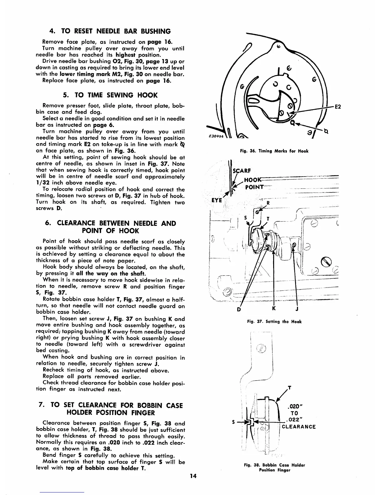
timing mark E2 on take-up is in line with
mark
on
face
plate,
as
shown
in Fig.
36.
At this setting,
point
of
sewing
hook
should
be
at
centre of needle,
as
shown in inset in Fig.
37.
Note
that
when
sewing hook is correctly timed, hook point
will be in centre of needle scarf
and
approximately
1/32
inch
above
needle eye.
To relocate
radial
position of hook
and
correct
the
timing, loosen
two
screws
at
D, Fig.
37
in
hub
of
hook.
Turn hook on its shaft,
as
required. Tighten two
screws
D.
6.
CLEARANCE
BETWEEN
NEEDLE
AND
POINT
OF
HOOK
Point of hook should pass needle scarf as closely
OS
possible
without
striking
or
deflecting needle. This
is achieved by setting a clearance
equal
to
about
the
thickness of a piece of note
paper.
Hook
body
should
always
be located, on
the
shaft,
by pressing it all the
way
on the shaft.
When it is necessary to move hook sidewise in rela
tion to needle, remove screv/ R
and
position finger
S, Fig.
37.
Rotate
bobbin
case
holder
T, Fig.
37,
almost
a half-
turn, so
that
needle will not contact needle
guard
on
bobbin
case
holder.
Then, loosen set screw J, Fig. 37 on bushing K
and
move entire bushing
and
hook assembly together, as
required; tapping bushing K
away
from needle (toward
right) or prying bushing K with hook assembly closer
to needle (toward left) with a screwdriver
against
bed
casting.
When
hook
and bushing are in correct position in
relation to needle, securely tighten screw J.
Recheck timing of hook,
as
instructed
above.
Replace all
parts
removed
earlier.
Check
thread clearance for bobbin cose holder posi
tion
finger
as
instructed
next.
7.
TO SET CLEARANCE FOR BOBBIN CASE
HOLDER
POSITION
FINGER
Clearance between position finger S, Fig. 38
and
bobbin cose holder, T,
Fig.
38 should be just sufficient
to allow thickness of thread to pass through easily.
Normally
this
requires
an
.020
inch to
.022
inch
clear
ance,
as
shown
in Fig.
38.
Bend finger S carefully to achieve this setting.
Make certain
that
top surface of finger S will be
level with top of bobbin case holder T.
14
Fig.
36.
Timing
Marks
for
Hook
SCARF
HOOK
POINT
D K J
Fig.
37.
Setting
the
Hook
y
:
.022
j
CLEARANCE
Fig.
38.
Bobbin
Case
Holder
Position
Finger