}
iL
B4
r 1 V
>'
• /
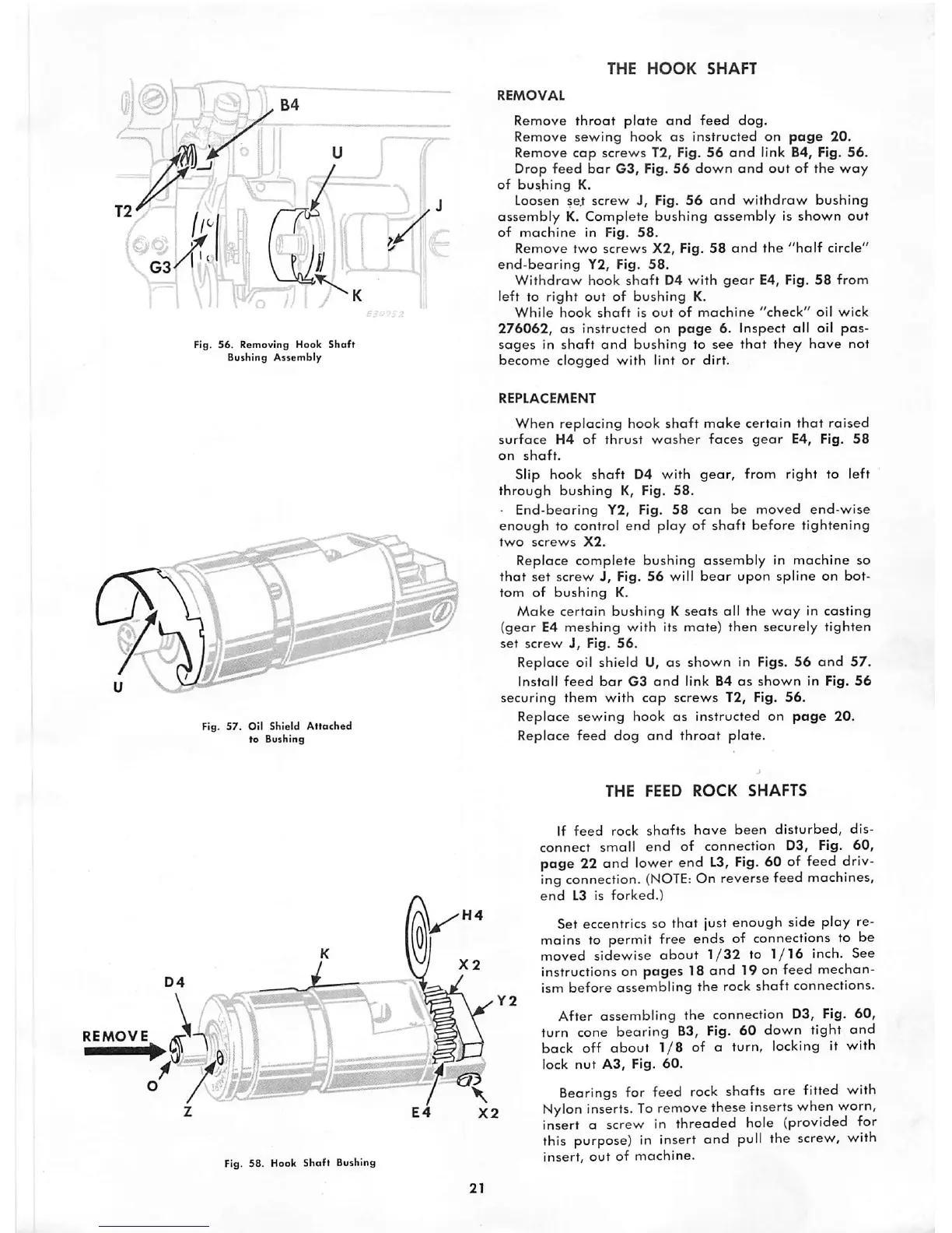
Fig.
56.
Removing
Hook
Shaft
Bushing
AssembI/
Fig. 57. Oil Shield
Attached
to
Bushing
Fig. 58. Hook Shaft Bushing
THE
HOOK
SHAFT
REMOVAL
Remove
throat
plate
and
feed
dog.
Remove
sewing
hook as instructed on
page
20.
Remove
cap
screws
T2, Fig.
56
and
link B4, Fig.
56.
Drop
feed
bar
G3, Fig. 56
down
and
out
of
the
way
of
bushing
K.
Loosen se.t
screw
J, Fig.
56
and
withdraw
bushing
assembly
K. Complete bushing assembly is shown
out
of
machine
in Fig.
58.
Remove
two
screws
X2, Fig.
58
and
the
"half
circle"
end-bearing
Y2, Fig.
58.
Withdraw
hook
shaft
D4
with
gear
E4, Fig.
58
from
left
to
right
out
of
bushing
K.
While
hook
shaft
is
out
of
machine
"check"
oil
wick
276062,
as instructed on
page
6. Inspect all oil
pas
sages
in
shaft
and
bushing
to
see
that
they
have
not
become
clogged
with
lint
or
dirt.
REPLACEMENT
When replacing hook
shaft
make
certain
that
raised
surface
H4
of
thrust
washer
faces
gear
E4, Fig.
58
on
shaft.
Slip hook
shaft
D4 with
gear,
from right to left
through
bushing
K, Fig.
58.
End-bearing
Y2, Fig.
58
can
be
moved
end-wise
enough
to control
end
play
of
shaft
before
tightening
two
screws
X2.
Replace
complete
bushing
assembly
in
machine
so
that
set
screw
J,
Fig.
56
will
bear
upon
spline
on
bot
tom
of
bushing
K.
Make
certain
bushing
K
seats
all
the
way
in
casting
(gear
E4
meshing
with
its
mate)
then
securely
tighten
set
screw
J,
Fig.
56.
Replace oil
shield
U, as
shown
in Figs.
56
and
57.
Install
feed
bar
G3
and
link B4
as
shown
in Fig.
56
securing
them
with
cap
screws
T2, Fig.
56.
Replace
sewing
hook as instructed on
page
20.
Replace
feed
dog
and
throat
plate.
X2
THE
FEED
ROCK
SHAFTS
If
feed
rock
shafts
have
been
disturbed,
dis
connect
small
end
of
connection
D3, Fig.
60,
page 22 and lower end
L3,
Fig.
60 of feed driv
ing connection.
(NOTE:
On reverse feed machines,
end
L3 is
forked.)
Set eccentrics so that just enough side play re
mains to permit free ends of connections to be
moved
sidewise
about
1/32
to
1/16
inch.
See
instructions on pages 18 and 19 on feed mechan
ism
before
assembling
the
rock
shaft
connections.
After
assembling
the
connection D3, Fig.
60,
turn cone bearing B3, Fig. 60 down tight
and
back off
about
1/8
of a turn, locking it with
lock
nut
A3,
Fig.
60.
Bearings for feed rock shafts
are
fitted with
Nylon
inserts.
To
remove
these inserts when worn,
insert a screw in
threaded
hole (provided for
this
purpose)
in insert and
pull
the
screw,
with
insert,
out
of
machine.