43
(1) (2) (3)
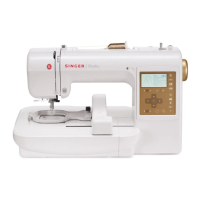
Step5
Velocity Sensor
000
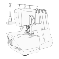
Step7
Foot Controller
000
[Faulty condition and remedy]
The screen does not change.
- Remedy –
Adjust the position of the shield
plate.
Adjust the position of the photo
sensor.
Replace the photo sensor or
circuit board A.
[Faulty condition and remedy]
The display does not change or
shows 413 or less.
- Remedy –
Clean up the photo sensor.
Adjust the position of the photo
sensor.
Replace the motor or circuit
board A.
[Faulty condition and remedy]
The display does not change or
indicates incorrect value.
- Remedy –
Replace the speed control lever,
circuit boards K or A.
[Faulty condition and remedy]
The display does not change or
indicates incorrect value.
- Remedy –
Replace the foot control, machine
socket or circuit board A.
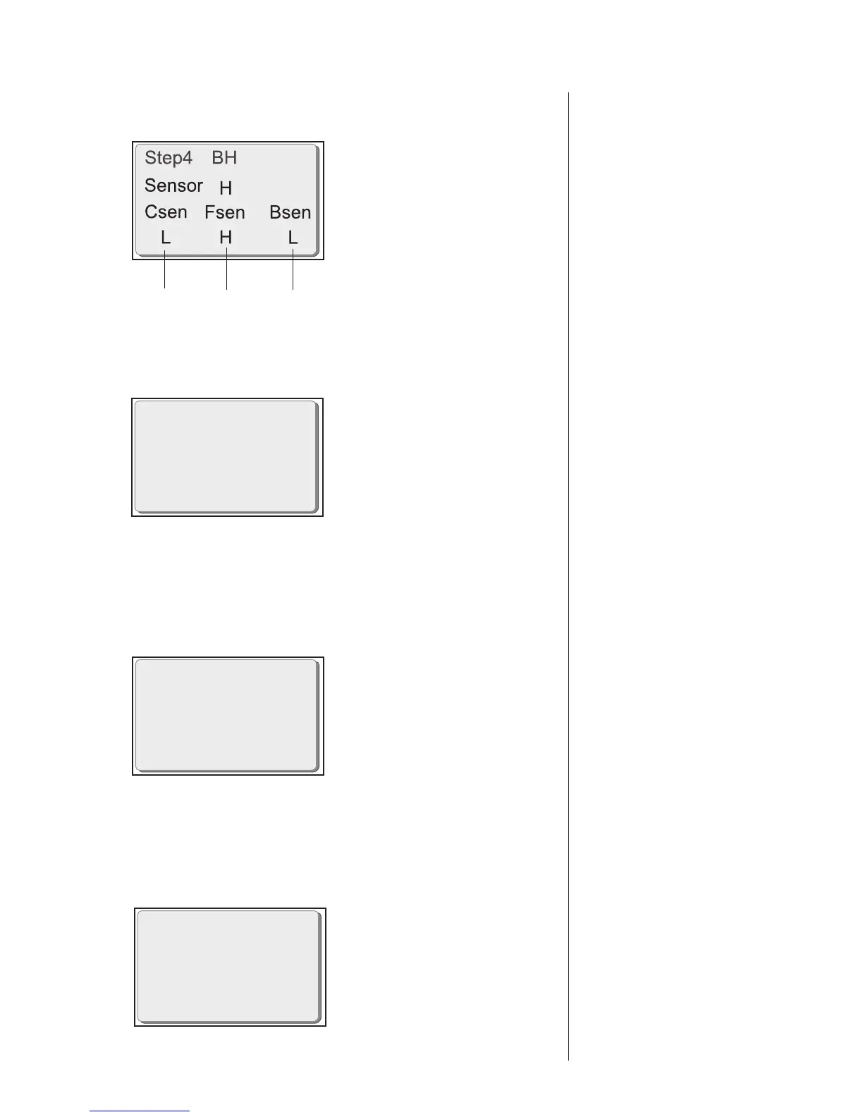
4. Step 4 (photo sensor)
[Correct condition]
The display shows [H] or [L].
Pull the buttonhole lever toward
you - [H]
Release the buttonhole lever - [L]
Push the buttonhole lever to the
back - [H]
Turn the hand wheel and see if
display changes to [H] or [L].
(1) Auto-thread cutter sensor
(2) Feed sensor
(3) Zigzag sensor
The “Csen” changes from “L” to
“H” at the lowest needle position.
[Correct condition]
Turn the hand wheel against you
slowly.
The display should show between
414 and 420.
Press the “Clear” button to
proceed to the next step.
[Correct condition]
Move the speed control lever
slowly.
The display shows:
At the left end: 000 - 002
At the right end: 253 – 255
[Correct condition]
The display shows:
000 – 016 when released foot
control.
208 – 250 when fully depressed.
251 – 255 when the foot control
is disconnected.
Press “Clear” button to proceed
to the next step.
5. Step 5 (speed sensor)
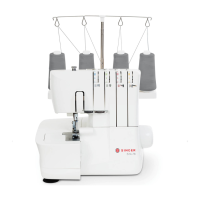
6. Step 6 (Speed control lever)
Step6
Volume
000
7. Step 7 (Foot control)



 To Next Page