22
OPERATING INSTRUCTIONS….cont
Once fully assembled and adjusted, and all safety precautions have been followed;
the pillar drill is ready to be run.
Your SIP pillar drill is fitted with a safety NVR (No Volt Release) switch. This means that if
the power is cut to the drill (such as in a power failure); the motor will not start to run
once the power is returned without the operator following the instructions below to re-
start the drill.
To start the drill - press the green (I) button.
To stop the drill - press the red (0) button or press down on the emergency stop cover.
ON / OFF (NVR) SWITCH
ADJUSTING THE SPEED - 01700 & 01701
Open the pulley cover.
Slacken off the belt tension lock.
Consult the chart inside the pulley cover, and position the belt on the pulley's ac-
cording to the spindle speed required.
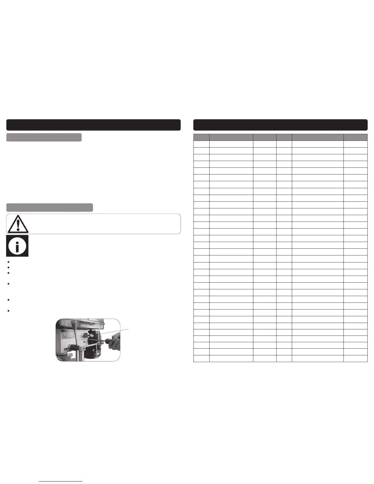
When the belt has been correctly positioned, re-tension by levering the motor
away from the head (024); Lever the motor with its bracket, away from the head,
so that tension is applied to the belt.
Tension is correct when the belt deflects by approx. ½” at its centre, when using
reasonable thumb pressure.
Lock the motor in this position using the belt tension lock.
Note: The speed of the pillar drill can be changed by adjusting the position
of the belt on the pulley system. See the chart inside the pulley cover for
speed configurations.
Danger: Before making any changes or adjustments, ensure that the drill is
turned off, and the mains lead is removed from the supply socket.
Belt Tension Lock
024
39
PARTS LIST - 01703
Ref. No. Description SIP Part No. Ref. No. Description SIP Part No.
1. Base WD01-00863 35. Motor plate WD01-00874
2. Column flange WD01-00864 36. Spring washer M12 WD01-00676
3. Spring washer M10 WD01-00795 37. Nut M12 WD01-00821
4. Bolt (M10 x 25) WD01-00796 38. Grub screw (M8 x10) WD01-00689
5. Rack WD01-00908 39. Motor pulley WD01-00876
6. Column WD01-00865 40. Motor WD01-00877
7. Grub screw (M6 x 12) WD01-00740 41. Nut M8 WD01-00687
8. Rack collar WD01-00799 42. Cam assembly WD01-00909
9. Screw (M6 x 16) WD01-00708 43. Washer WD01-00878
10. Handle cap WD01-00800 44. Protecting ring WD01-00839
11. Screw (M8 x 20) WD01-00801 45. Speed label WD01-00879
12. Spring washer M8 WD01-00673 46. Pulley cover WD01-00880
13. Handle knob WD01-00802 47. Microswitch WD01-00706
14. Handle WD01-00803 48. Washer M5 WD01-00881
15. Label WD01-00893 49. Spring washer M5 WD01-00882
16. Knob WD01-00867 50. Nut M5 WD01-00697
17. Scale WD01-00805 51. Nut M6 WD01-00710
18. Connection WD01-00806 52. Spring washer M6 WD01-00707
19. Pinion shaft WD01-00809 53. Washer M6 WD01-00702
20. Roll pin (5 x 16) WD01-00868 54. Microswitch holder WD01-00709
21. Warning label WD01-00685 55. Eccentric shaft WD01-00883
22. Screw (M5 x 10) WD01-00726 56. Centre pulley WD01-00884
24. Roll pin (5 x 25) WD01-00869 57. Bearing 6202 WD01-00771
25. Roll pin (6 x 18) WD01-00760 58. Circlip WD01-00831
26. Locking handle WD01-00870 59. Belt O-565 WD01-00833
27. Belt tension handle WD01-00812 60. Knurled screw WD01-00885
28. Circlip WD01-00813 61. Circlip WD01-00704
29. Circlip WD01-00871 63. Screw (M5 x 16) WD01-00838
30. Shaft WD01-00872 64. Mains lead clamp WD01-00700
31. Adjusting shaft WD01-00873 65. Protecting ring WD01-00770
32. Washer M12 WD01-00819 66. Belt O-678 WD01-00886
33. Bolt (M8 x 25) WD01-00695 67. Spindle pulley WD01-00887
34. Washer M8 WD01-00672 68. Circlip WD01-00713
 Loading...