Operation instructions
SIPOS 5 PROFITRON, HiMod
Page 10 Y070.020/GB
3 Assembly and connection
3
Assembly and connection
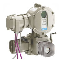
5. Lubricate axial needle-roller bearings and axial
bearing washers (3) with ball bearing grease and
fi t them on the new or machined stem nut (4).
6. Insert stem nut (4) with axial needle-roller as-
sembly into output fl ange (claws have to engage
properly into the groove of the output shaft of the
actuator).
7. Screw in the centering ring (5) and tighten it as
far as the stop.
Make sure the radial seal is inserted correctly (6).
8. Using a grease gun, press ball bearing grease
into the grease nipple (2) until lubricant is dischar-
ged between the centering ring (5) and the stem
nut (4).
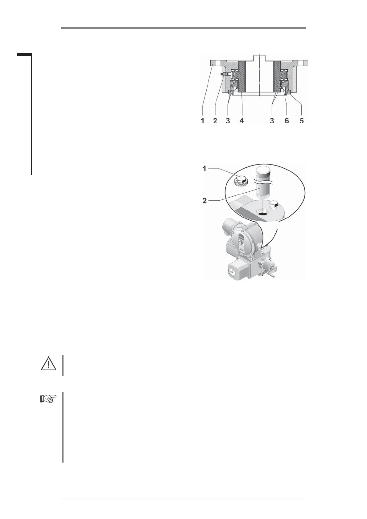
3.1.3 Mount spindle protection tube
1. Remove fastener (fi g., item 1).
2. Check that the extended stem does not exceed
the length of the protective tube.
3. Apply sealing compound to the thread and the
sealing faces (e.g. 732 RTV from Dow Corning,
Munich, Germany).
4. Screw in the spindle protection tube (2).
Fig.: Output shaft type A installed
Fig.: Mounting the spindle protection
tube
3.2 Electrical connection
The components are designed as to ensure that once connected correctly, uninsulated, live parts
cannot be touched directly; i.e. protection against electric shock is provided in accordance with
IP2X or IPXXB .
Dangerous voltages are also present when the motor is at a standstill. Before opening the
terminal cover or the connection hood, disconnect the supply voltage from the actuator. Allow 5
minutes for the capacitors to discharge and do not touch any contacts.
■
The supply voltage must always lie within the voltage range specifi ed on the rating plate.
■
Mains cable: Use metal cable glands for mains connection.
■
Signal cable: Use metal cable glands with cable shielding for the connection of the control
cable to avoid the occurrence of electronic faults. The signal cable must be shielded and the
shield must be fi xed or earthed on both sides. Ensure careful connection of the screen within
the cable gland!
■
It must be ensured that the cable glands and seals (O-rings) are fi tted carefully and correctly
in order to guarantee the enclosure protection. For details of the permissible conductor cross-
sections, see wiring diagram.
■
Cable glands and cables are not included in the scope of delivery.
 Loading...