TECHNICAL DATA
DESCRIPTION
•
Gas connections inlet 1/2 or 3/8 - outlet 3/8 Rp ISO 7
•
Installation position any
•
Gas families I,II and III
•
Maximum gas inlet pressure 50 mbar
•
Outlet pressure setting range (optional) 3-18 mbar (15-30 mbar)
•
Working temperature range 0-80 °C
•
Pressure regulator (optional) optional class C
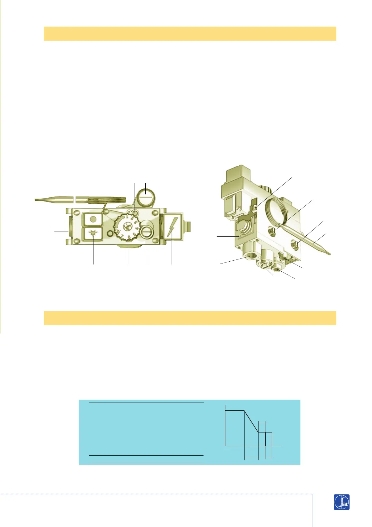
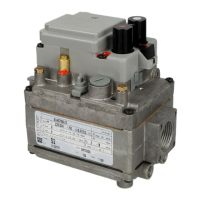
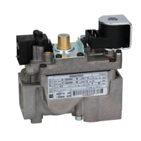
8 Oulet pressure setting screw (versions
with flow regulator)
9 Inlet pressure test point
10 Outlet pressure test point
11 Thermocouple connection
12 Pilot outlet
13 Gas inlet
14 Main gas outlet
15 Flange fixing holes (M5)
16 Fixing points
17 Thermostat bulb
1 Ignition button
2 Shut-down button
3 Piezo-electric ignition button
(optional)
4 Temperature setting knob
5 Screw for adjusting gas flow to pilot
6 Minimum flow setting screw
7 Maximum flow setting screw
(versions with flow regulator)
Thermostat range
a b c
8-33 °C 3 3 2
13-31 °C 2 2 2
13-38 °C 3 3 2
13-48 °C 4 4 3
21-46 °C 3 3 2
30-100 °C 9 9 5
40-72 °C 5 5 3
40-80 °C 5 5 3
100-340 °C 30 30 10
Other ranges are available on request
Data refer EN 126 standard
1
5 8
2
13
4 6 3
15
16
10
9
17
14
12
11
7
(Version with pressure regulator) (Version with flow regulator and bottom gas outlet)
Gas flows
Temperature