Document NO.:RD-508C-39-001
Version: E 20170920
- 6 -
Diagram 4
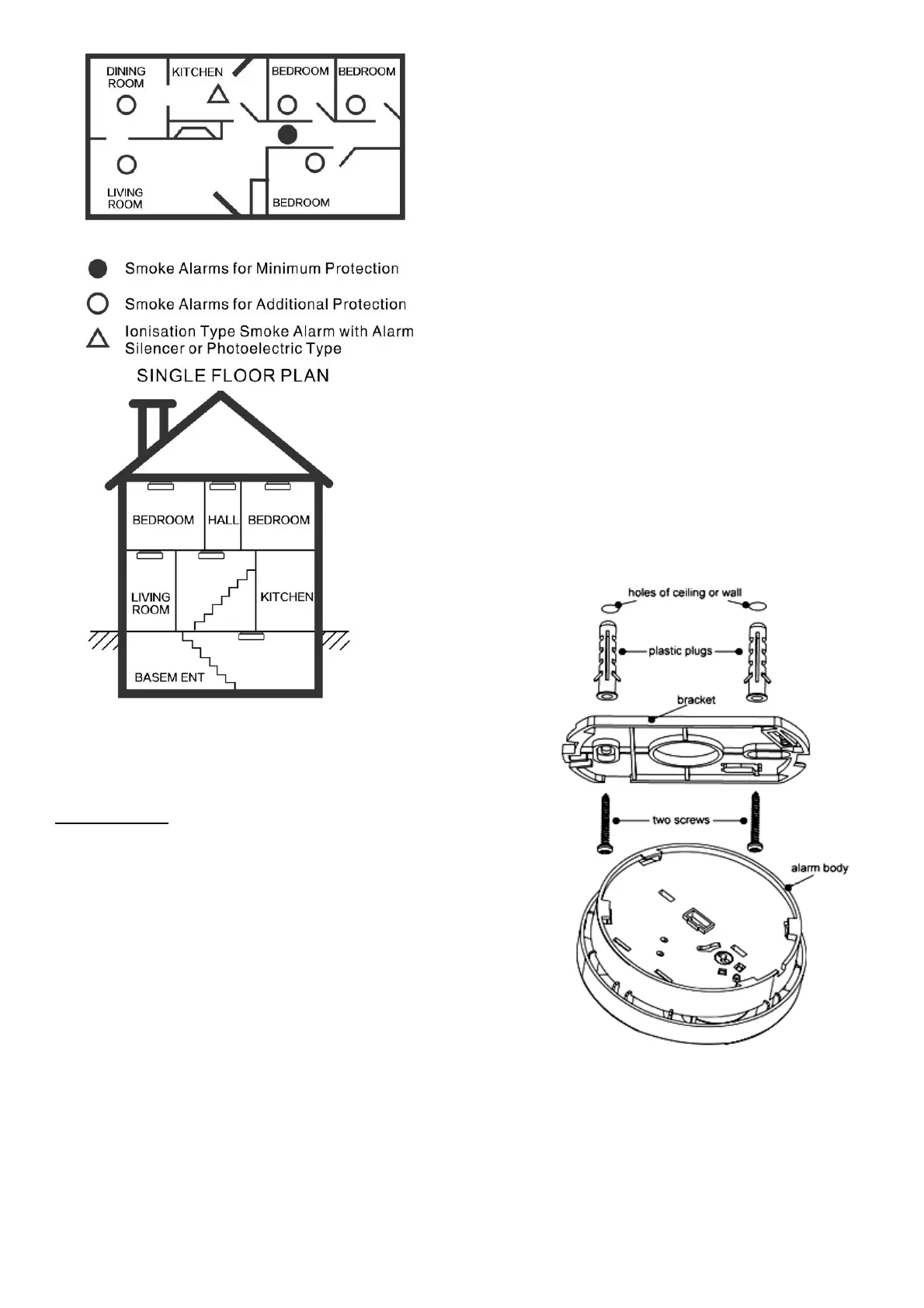
MULTIPLE FLOOR PLAN
Diagram 5
Installation:
Activation
Press test button and hold it for more than 3 seconds
until LED lights, and release it within 2 seconds, the unit
will generate a “beep” indicating that it is activated and
ready to detect status.
CAUTION: this unit must activated prior to installation.
Failure to perform step will result in a non functioning
smoke alarm!
• Turn the alarm body counterclockwise and take off the
bracket.
• Hold the bracket in the installation position as specified in
the Recommended Locations, mark installation holes of the
bracket with pencil.
• Drill the two marked installation holes with a 3/16 inch
(5mm) drill bit. Tap the two plastic grommets into holes
with hammer.
• Remove locking plug from the bracket with screwdriver if
necessary (Refer to Diagram 6). This is an optional
additional locking in place feature.
• Mount the bracket to the ceiling by inserting and tightening
the supplied screws into plastic grommets. (Refer to
Diagram 7).
• Fit the alarm on the bracket and turn the alarm body
clockwise, until fully inserted on the bracket.
• Optionally insert locking plug into the gap between bracket
and bottom cover for locking alarm in place (Refer to
Diagram 8).
• Press the button to test the unit. The alarm should then
sounds 3 beeps – 1.5 seconds pause, and will repeat until
the button is released, if no sound, it indicates a defective
alarm, refer to the ”Trouble shooting” section for a solution
or return to your retailer during warranty.
WARNING:
To prevent injury, this unit must be securely attached to the
wall or ceiling in accordance with the installation instructions.
Diagram 7
 Loading...