REV. 02 22 / 30
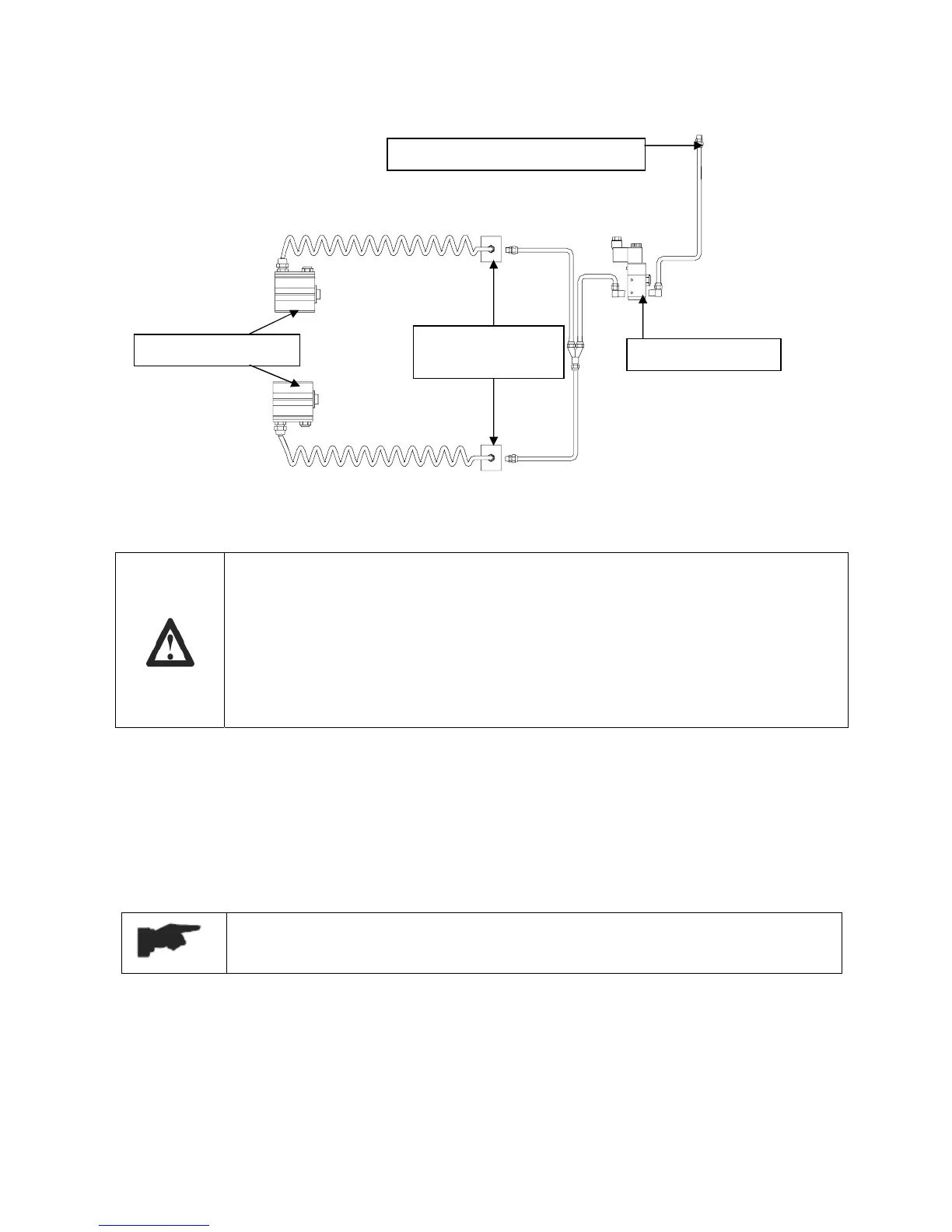
Figure 15 – PNEUMATIC CONNECTIONS
A
PR
7.7 MAKE ELECTRICAL HOOKUP TO HYDRAULIC POWER UNIT
The hookup work must be carried out by a qualified electrician.
Make sure that the power supply is right.
Make sure the connection of the phases is right. Improper electrical hook-up can
damage motor and will not be covered under warranty.
DO NOT run the hydraulic unit with no oil. Damage to pump can occur.
The control unit must be kept dry.
• Make the electric hookup to the hydraulic power unit referring to the attached wiring diagram
(figure 5) using the included cables;
• Make sure the connection of the phases is right and the lift is grounded (if no special request,
normally, black wires are for phase lines, the blue is for “0” line and the yellow/green is for
grounding).
7.8 START AND BLEEDING
Do not install the maximum working height limit switch before bleeding the
hydraulic line.
During this procedure, DO NOT attempt to raise lift with any load.
7.8.1 START
• Make sure all pins and bolts to insure proper mounting
• Make sure the electrical system feeding voltage is equal to that specified in the nameplate on
the motor
• Make sure the electric connections are in compliant with diagrams figure 5
• Make sure no leakage or blow-up in hydraulic line and pneumatic line
To the water separator/lubricator
Pneumatic cylinders
Solenoid air valve
Air block placed
on each base