REV. 02 24 / 30
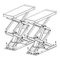
7.9 ANCHORING THE BASE FRAMES
• Place the lift at a height about 1m;
• Using the base frames as guide, drill each hole in the concrete approximately 120mm deep
with the rotary hammer drill D.16. To assure full holding power, do not ream the hole or
allow drill to wobble;
• After drilling, remove dust thoroughly from each hole using compressed air or wire brush;
• Assemble the washers and nuts on the anchors then tap into each hole with a hammer until the
washer rests against the base plate.
• Verify that the platform is leveled horizontally by means of a water gauge or an air bubble;
• If shimming is required, insert the shims as necessary around the anchor bolts.
• With the shims and the supplied anchor bolts in place, tighten by securing the nut to the base.
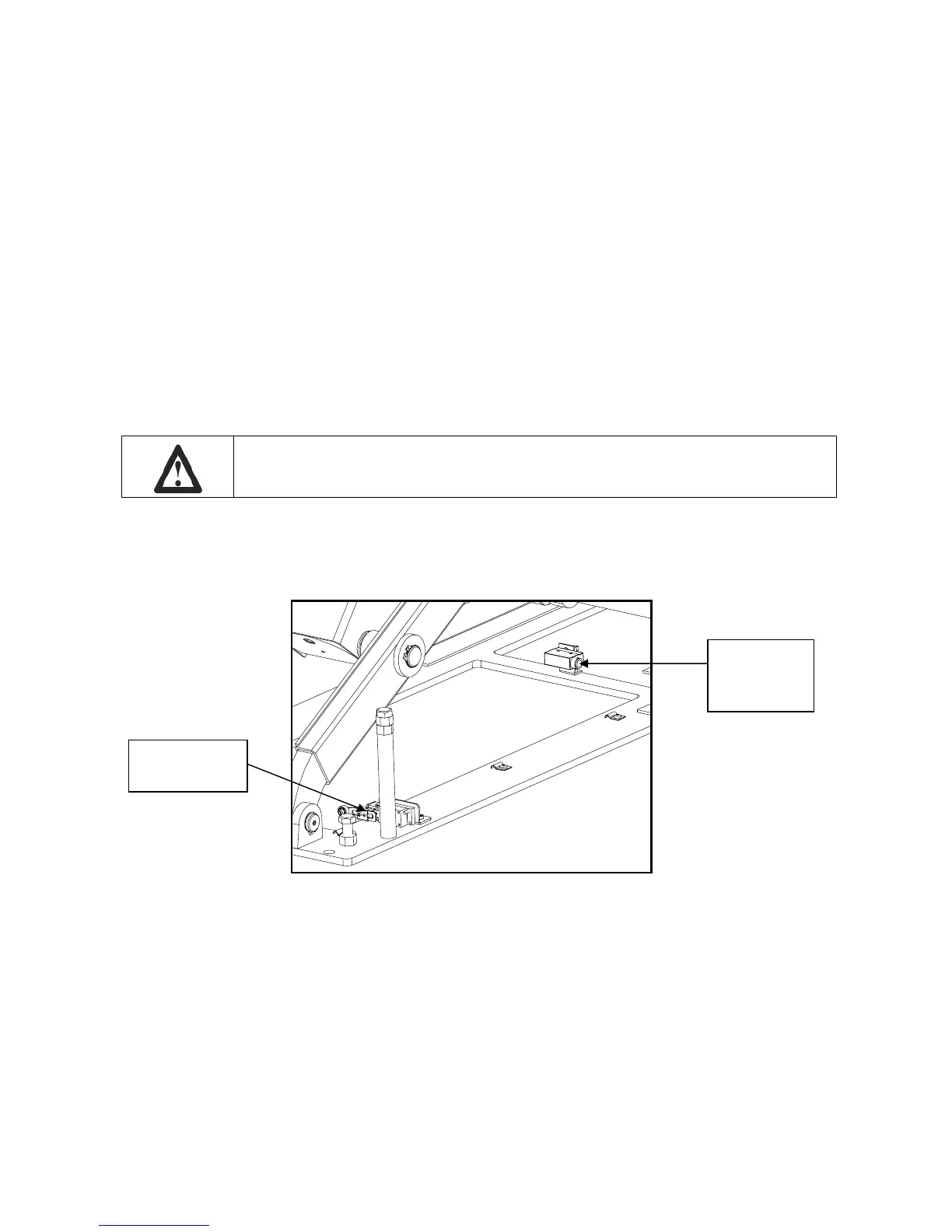
7.10 INSTALLATION AND ADJUSTMENT OF LIMIT SWITCHES
Only skilled personnel must be allowed to carry out this operation. An
improper adjustment of limit switches could cause damages to the lift, objects
and people.
7.10.1 INSTALLATION OF LIMIT SWITCHES
• Fix the limit switches on the brackets as shown in the figure 17 using the included screws.
7.10.2 ADJUSTMENT OF MAX. LIFTING HEIGHT LIMIT SWITCH
• Place the lift at a height of 2060 mm.
• Unloose nuts and adjust it at the desired height;
• Tighten the screws after adjustment.
7.10.3 ADJUSTMENT OF SAFETY HEIGHT LIMIT SWITCH
• Place the lift at a height of 400 mm;
• Unloose screws of the lever and adjust its position to meet the desired height;
• Tighten the nuts after adjustment.
Max. lifting
height limit
switch
Safety height
limit switch
Fig. 17