Do you have a question about the SIYI N7 and is the answer not in the manual?
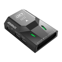
The SIYI N7 Autopilot is a flight controller designed for professional application scenarios, offering a robust and reliable solution for various unmanned vehicles and ships. It is equipped with an H7 double-precision floating-point unit processor, which integrates a built-in dual IMU redundancy and internal shock absorption structure design, contributing to high reliability. The N7 flight controller is compatible with both ArduPilot and PX4 open-source ecosystems, enabling a wide range of application scenarios and providing stable and comprehensive systematic solutions for enthusiasts and industry application explorers.
Hardware:
Sensors:
External Interface:
Overall:
The N7 Autopilot offers a comprehensive set of features for flight control and configuration.
First Time Setup: Users are welcomed to visit the official ArduPilot documentation for step-by-step instructions. For ground control, the Mission Planner GCS software is recommended. Firmware upgrades are performed by connecting the N7 autopilot to a computer via a USB port (Type-C to USB-A cable) and using Mission Planner to detect and upload the appropriate firmware. It's crucial to select the correct vehicle or frame type during firmware installation.
Mounting the Autopilot: The autopilot should be placed close to the center of gravity of the vehicle, both horizontally and vertically. The GPS module should be mounted separately from the flight controller, with a clear view of the sky and away from motors and ESCs. The recommended orientation is to mount the module with the arrow facing toward the front of the vehicle.
Motor Order Diagrams: The manual provides diagrams for common frame types (QUAD X and HEXA X) to illustrate the correct motor numbering and direction (clockwise, CW, or counter-clockwise, CCW).
Vibration Damping: Autopilots are sensitive to vibrations. The N7 includes internal anti-vibration structure, but external anti-vibration boards can be used for further damping. Advice for reducing vibrations includes ensuring frame flex is minimal, motors are securely mounted, propellers are balanced, and soft cables are used for connections.
Magnetic Interference: Magnetic interference can seriously impact navigation. Multi-rotor drones should avoid placing RTK modules instead of GPS compass. To reduce interference, users should use an external compass, keep power distribution board, ESC, and battery as short as possible, wrap wires between distribution board, ESC, and battery, and replace the distribution board and ESC with 4-in-1 ESCs. Adding aluminum foil shielding around the ESC to motor cable may reduce AC interference.
Mandatory Hardware Configuration: The N7 autopilot is designed for the SIYI ecosystem based on ArduPilot. Users are encouraged to visit the ArduPilot documentation for configuring hardware. This includes:
First Flight & Tuning: Before the first flight, users should perform pre-arm safety checks, which include verifying firmware, 3D Accel calibration, safe switch, RC calibration, and barometer health. Common reasons for arm failure include compass offsets, GPS glitch, and accelerometer/gyro issues.
Arming and Disarming: Arming the vehicle involves allowing the motors to start spinning. This is done by turning on the remote controller, plugging in the LiPo battery, checking RGB LED status, verifying flight mode switch, pressing the safe switch, and then holding the throttle down and rudder right for 5 seconds. Disarming involves checking flight mode, holding throttle at minimum and rudder to the left for 2 seconds, and disconnecting the battery.
Tips for New Operators: This section provides advice on initial flying strategies, including placing the copter on level ground, ensuring RC mode toggle switch is in Stabilize mode, checking for unexpected yaw, and avoiding pronounced wobble. Tips for the first flight include flying in a wind-free environment, making sure the radio is trimmed, holding the copter still and level after connecting the battery, and getting above ground effect.
Measuring Vibration: Ground Stations can display a real-time view of vibration and clipping. Vibration levels below 30m/s/s are normally acceptable. The Mission Planner can graph VIBE messages (VibeX, VibeY, VibeZ values) to show the standard deviation of the primary accelerometer's output.
Thrust Loss and Yaw Imbalance Warnings: These warnings indicate hardware failures in the propulsion system. Potential thrust loss messages are seen on the GCS or in data-flash logs. Yaw imbalance warnings indicate issues with the vehicle's ability to maintain yaw.
Advanced Configurations: This section covers parameters like BATT_ARM_VOLT (required arming voltage), BATT_ARM_MAH (required arming remaining capacity), BATT_LOW_VOLT (low battery voltage), BATT_LOW_MAH (low battery capacity), BATT_LOW_TIMER (low voltage timeout), BATT_FS_LOW_ACT (low battery failsafe action), BRD_SAFETY_DEFLT (sets default state of the safety switch), ARMING_RUDDER (arming with rudder enable/disable), LOG_BACKEND_TYPE (logger backend storage type), LOG_BITMASK (log bitmask), ARSPD_AUTOCAL (airspeed parameter), GPS_TYPE (GPS type), FS_THR_ENABLE (throttle failsafe enable), BATT_LOW_VOLT (low battery voltage), BATT_FS_LOW_ACT (low battery failsafe action), and AHRS_ORIENTATION (board orientation).
Logs: The N7 records flight data, which can be downloaded from the autopilot after a flight. Telemetry logs are also known as "Tlogs" and are recorded by the ground station. Common parameters for flight logs include LOG_BACKEND_TYPE, LOG_BITMASK, LOG_DISARMED (enable logging while disarmed), LOG_FILE_DSRMROT (stop logging to current file on disarm), LOG_FILE_MB_FREE (old logs on the SD card will be deleted to maintain this amount of free space), and LOG_FILE_RATEMAX (maximum logging rate for file backend).
After-sale Service: For any questions or problems using SIYI Technology's product, users can send an email to SIYI Official A/S Center (support@siyi.biz) or consult their sales representative or dealer.
Repair Service: If SIYI products cannot work properly, users should contact SIYI Official A/S Center for consulting. There are two situations for acquiring repair service:
Warranty: SIYI Technology guarantees the following conditions: Return & Refund Service, Replacement Service, and Warranty Repair Service.
Warranty Repair Service will not be provided where:
| Brand | SIYI |
|---|---|
| Model | N7 |
| Category | Autopilot System |
| Language | English |