SKF Copperhead Transmitter Unit CMPT CTU 4-11
Dimensions/Front panel/Terminals
Connector Assignment
Instruction Manual
Connector Assignment
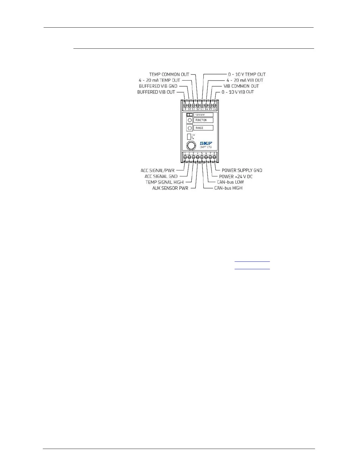
Figure 4-3: CMPT CTU connector assignment
Pin Number Connection Description
1 ACC SIGNAL/PWR Accelerometer signal
2 ACC SIGNAL GND Accelerometer ground
3 TEMP SIGNAL High Temperature signal (optional)
4 AUX SENSOR PWR Powering of auxiliary sensor
(optional)
5 CAN-bus HIGH See CTU CAN-bus
6 CAN-bus LOW See CTU CAN-bus
7 POWER +24 V DC Power supply for CTU
8 POWER SUPPLY GND Power supply ground
9 BUFFERED VIB OUT Buffered (not processed) vibration
signal
10 BUFFERED VIB GND Buffered vibration signal ground
11 4–20 mA TEMP OUT Analog signal for temperature
12 TEMP COMMON OUT Common (ground) for temperature
13 0–10 V TEMP OUT Analog signal for temperature
14 4–20 mA VIB OUT Analog signal for processed
vibration
15 VIB COMMON OUT Analog signal common (ground) for
vibration
16 O–10 V VIB OUT Analog signal for processed
vibration
 Loading...