SKF Copperhead Transmitter Unit CMPT CTU 7-17
Basic Instructions and Wiring Connections
Instruction Manual
Basic Instructions and Wiring Connections
7
General Instructions
The accelerometer sensor and CMPT CTU should be located within 100 m (300 feet) of
each other. A suitable twisted and shielded pair of wires (22 AWG with 100 pF/m)
should be used to connect the CMPT 2310 and CMPT 2323 accelerometer sensors to
the CTU. Three wires are needed for the CMPT 2310T and CMPT 2323T sensors.
Set the CTU rotary FUNCTION and RANGE switches to configure the transmitter for the
desired vibration analysis mode and the desired output signal scale. The FUNCTION
switch setting defines the type of vibration analysis (Acceleration Enveloping,
Acceleration, or Velocity) and the RANGE setting defines the output signal scale. The
RANGE setting also defines the type of input source (accelerometer sensor or a buffered
signal input from another CTU).
The CTU can be mounted horizontally or vertically on a DIN rail. It is advisable to use
DIN spacers between the CTU modules. The CTU must be installed in an area with
sufficient cooling.
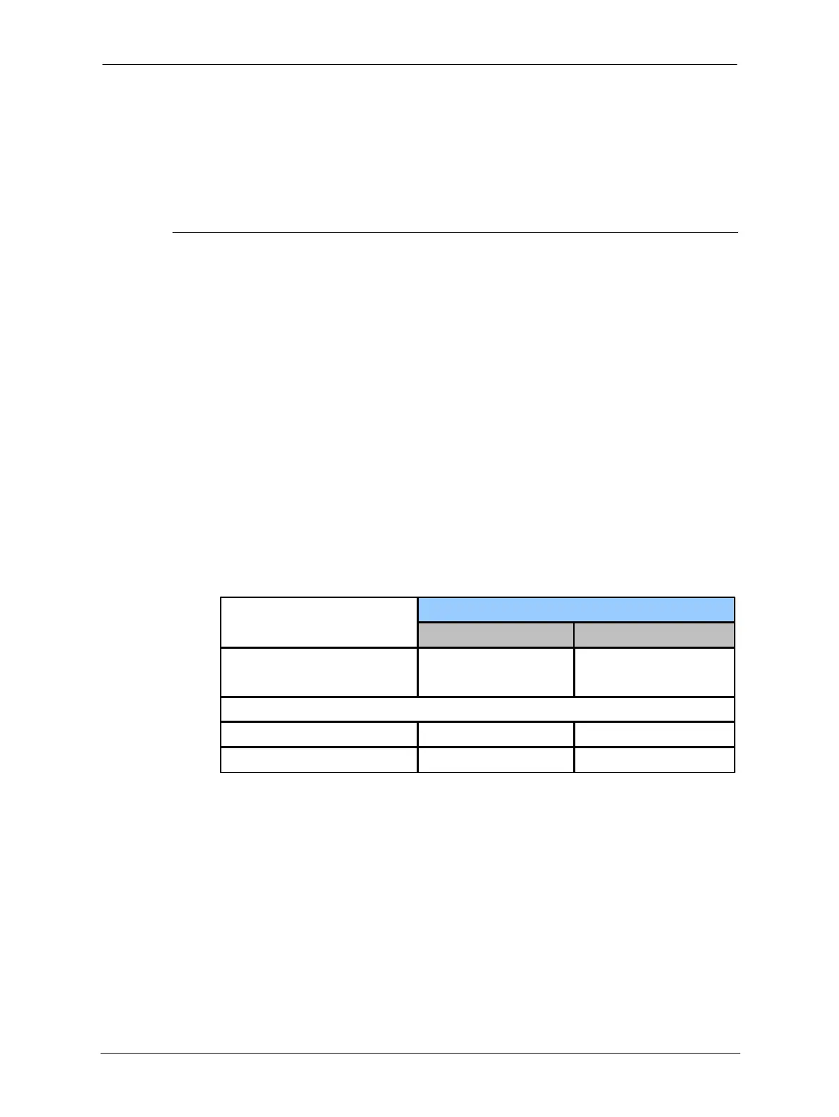
The following Table 7-3 shows general recommendations on the selection of the
vibration accelerometer and the RANGE and signal decay settings for the CTU
depending on the speed of the application.
Table 7-3: CTU application conditions
The analog output signals can be averaged using the appropriate RANGE switch setting.
This will reduce the variation of the signal display for visual observation with a CMPT
DCL display/alarm module or in the PLC/DCS system.
After the CTU FUNCTION and RANGE switches are set, apply the self-adhesive stickers
provided with the CTU to the front panel of the CTU corresponding to the selected
FUNCTION and RANGE settings.
 Loading...