SKF Copperhead Transmitter Unit CMPT CTU 6-13
CMPT CTU Output Signal Scales
Instruction Manual
CMPT CTU Output Signal Scales
6
Vibration
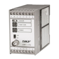
The accelerometer sensor and CMPT CTU unit provide processed vibration and
temperature (optional) analog signals for use with a CTU module and for PLC/DCS
systems for continuous monitoring. The scale of the CTU vibration analog output signal
in engineering units (gE, g, mm/s or inch/s (IPS)) depends on the setting of the rotary
FUNCTION and RANGE switches and the sensitivity of the selected accelerometer
sensor. See Table 6-1 and Table 6-2 below for the full scale (RANGE) values of the CTU
depending on the type of vibration analysis mode, sensor sensitivity, and selected CTU
RANGE.
Examples for the setting of the FUNCTION and RANGE:
Example 1
Sensor 100 mV/g
CTU settings
FUNCTION switch C (Acceleration Enveloping ENV 3)
RANGE switch 2 (full Scale = 30 gE)
Output signal scale
Vibration 0–30 gE3 (4 to 20 mA and 0 to 10 V DC)
Temperature 0–120 °C (4 to 20 mA and 0 to 10 V DC)
Example 2
Sensor 100 mV/g
CTU settings
FUNCTION switch 0 (Velocity ISO)
RANGE switch 2 (full Scale = 15 mm/s)
Output signal scale
Vibration 0–15 mm/s (4 to 20 mA and 0 to 10 V DC)
Temperature 0–120 °C (4 to 20 mA and 0 to 10 V DC)
Example 3
Sensor 230 mV/g
CTU settings
FUNCTION switch C (Acceleration Enveloping)
RANGE switch 0 (full Scale = 1,3 gE3)
Output signal scale
Vibration 0–1,3 gE3 (4 to 20 mA and 0 to 10 V DC)
Temperature 0–120 °C (4 to 20 mA and 0 to 10 V DC)
 Loading...