SKF Copperhead Transmitter Unit CMPT CTU 10-27
CTU CAN-bus
CTU CAN Protocol
Instruction Manual
CTU CAN Protocol
The CTU protocol will be specified in the following sections. Note that the OSI layer
descriptions are an indication of where the protocols must be specified according to the
7-layer model.
CTU’s are defined to operate on 250 kBit/s and this cannot be changed.
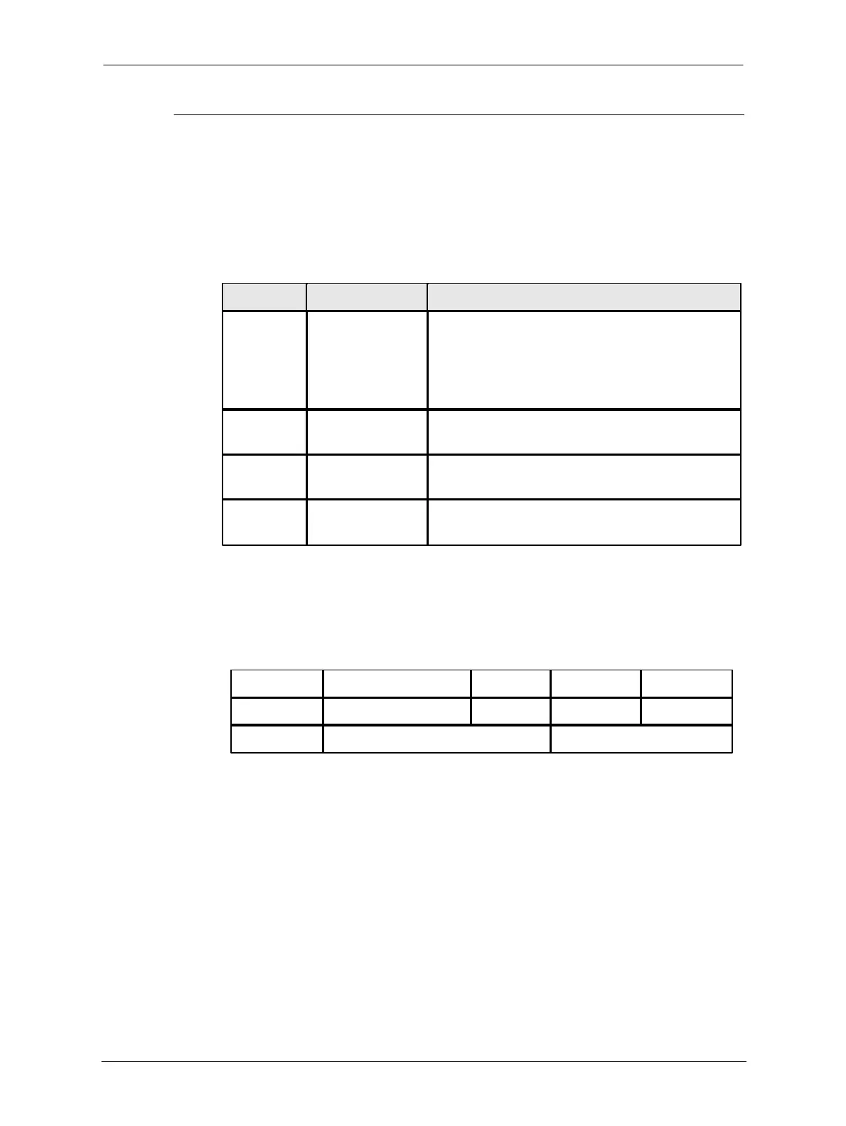
Used CAN message contains following information:
CAN message ID
Lower 29 bits are used for extended frame format
messages.
Bits 29 – 19 are used for standard frame format
messages.
0 = standard frame format (11-bit ID)
1 = extended frame format (29-bit ID)
Data Length Code, length of the Data field in bytes
(min 0, max 8)
Message data bytes. Byte send order is Data[0],
Data[1], …, Data[7].
Table 10-8: Used CAN messages
CTU uses the extended frame format.
The CAN extended frame ID format consisting of 29-bits is as following:
Table 10-9: CAN extended frame ID fromat consisting of 29-bits
As shown in Table 10-9 above, the network layer uses the ID bits [28-25] and [15-0]
for protocol communication. The CTU service layers (higher layers) use bits [24-16] and
the DLC and Data bytes from the CAN message.
 Loading...