CTU CAN-bus
CTU CAN-bus Connection
SKF Copperhead Transmitter Unit CMPT CTU10-26
Instruction Manual
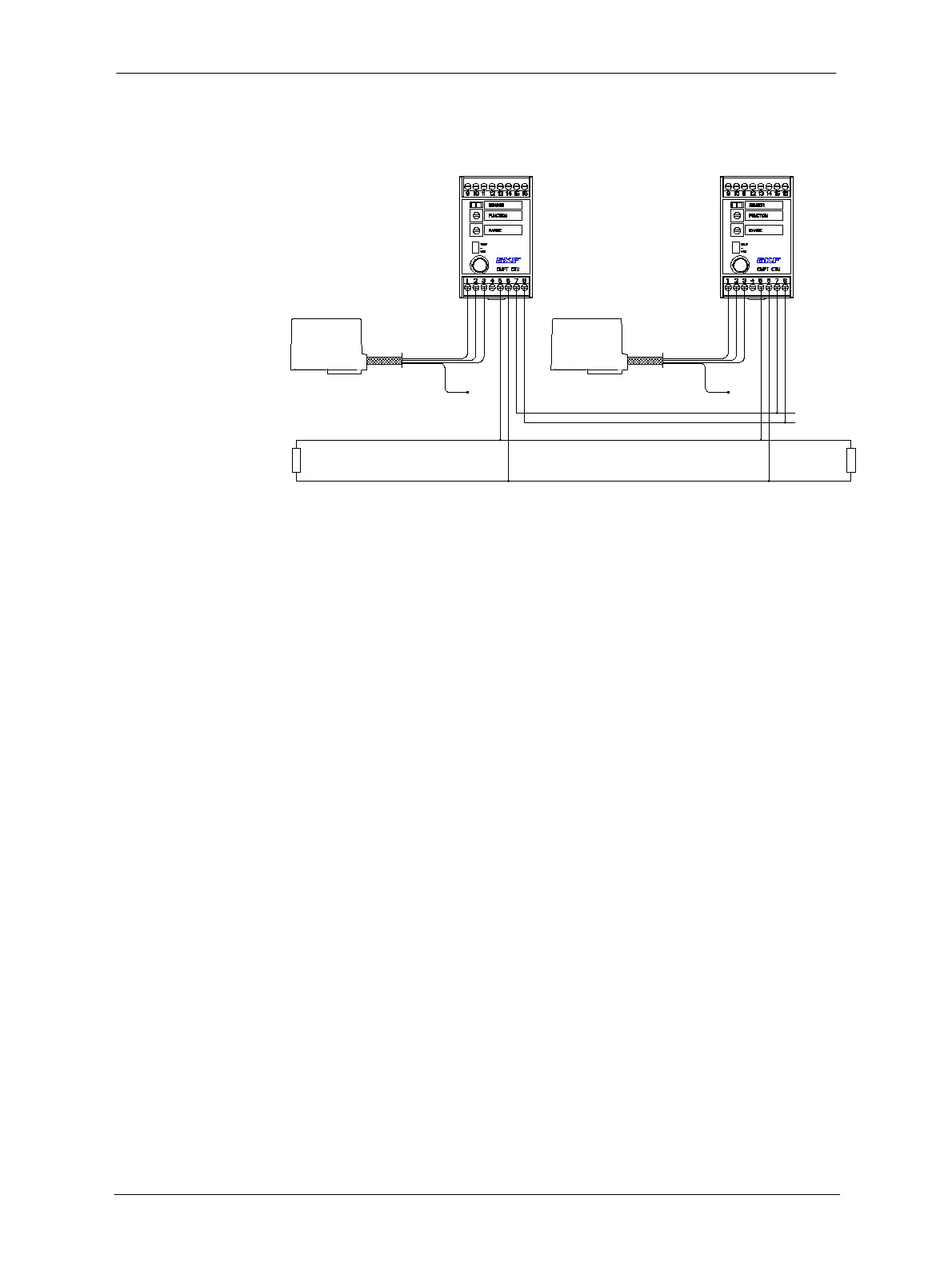
The CAN-Bus has to be terminated with 120 Ω on both ends as shown in Figure 10-8,
below. The can-bus cable should be a two-wire twisted pair. Wires between each unit
must be as short as possible. If wires are too long, perturbation may appear on the bus
and alter the data.
120 Ohm
120 Ohm
CANBUS High
CANBUS Low
Power +24 VDC
Power GND
GND GND
Figure 10-8: Two CTU transmitters wired for CAN-bus connectivity
Network problems are often caused by not using proper termination at both ends,
wrong bit rates for cable lengths, incorrectly installed cables and/or poor signal quality.
For more information, refer to:
"Controller Area Network", by Konrad Etschberger, ISBN N 3-00-007376-0
http://en.wikipedia.org/wiki/Controller%E2%80%93area_network
 Loading...