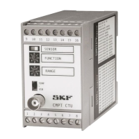
SKF Copperhead Transmitter Unit CMPT CTU 2-5
Features
Instruction Manual
Features
2
· Suitable with accelerometer sensors (10 mV/g to 230 mV/g).
· Temperature converter for accelerometers with integral temperature sensors.
· Three user selectable vibration process analyses:
- SKF Acceleration Enveloping (ENV3), gE
- Acceleration (RMS and Peak Hold), g
- Velocity ISO, mm/s (inch/s)
· User configurable features on the front panel:
- Vibration analyzer
- Output Range
- Optional sensor input or buffered vibration output input
- Optional signal decay for Acceleration Enveloping Peak hold
- Optional output signal averaging.
· Analog output signals - Processed vibration and temperature for interface with
PLC/DCS and CMPT DCL alarm/display monitors.
· 35 mm DIN rail mounted with rugged steel retainer clip.
· Front panel mounted BNC connector for buffered vibration and temperature
measurements.
· Front panel sensor OK/Overload lamp for detection of sensor and CTU faults.
· CAN-bus interface for connectivity of multiple numbers of CTU and remote
monitoring via computer.
· Internal isolated DC/DC converter for grounding loop and reverse polarity
protection.
· Auxiliary 24 V DC voltage output for optional powering of other sensor types
(tachometer).
The software to process the vibration and temperature signals is embedded into the
digital signal processing (DSP) card in the CTU. Calibration of the CTU is a part of the
embedded software.
The CTU unit has two front panel rotary switches to set the configuration. There is no
need to open the CTU enclosure to adjust pins or jumpers. The BNC connector is front
panel switchable (BNC switch) to measure either the accelerometer sensor buffered
(not processed) vibration output or the sensor temperature output. The buffered
vibration output can be monitored with an SKF Microlog or equivalent device.
The CTU has a user configurable option to average the analog output signals so that
rapid changes in vibration input do not cause annoying fluctuations in PLC/DCS or
digital displays.
The CTU has a user configurable option of 1 second or 10 second signal decay time for
Acceleration Enveloping Peak hold. The 10 second signal decay time is recommended
for low speed (n <40 r/min) applications where the frequency of the mechanical impact
vibration is low. Normal operation of the CTU is with the 1 second signal decay time.
The CTU can be user configured to accept a constant current signal from another CTU
operating with an accelerometer sensor. This enables two CTUs having different
configurations such as one Acceleration Enveloping and one Velocity to monitor the
same accelerometer sensor signal.
 Loading...