Features
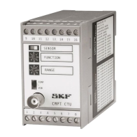
SKF Copperhead Transmitter Unit CMPT CTU2-6
Instruction Manual
The CTU has a front panel mounted SENSOR OK lamp to indicate that the sensor is
correctly connected to the CTU and that the sensor (accelerometer and temperature)
and the CTU are operating correctly.
- Green indicates that the system is OK (Correct).
- Red indicates that the system has a fault with the sensor or CTU, or that the
vibration level or temperature exceeds the set RANGE (overload).
The CTU can be located up to 100 m (330 feet) from the sensor with suitable shielded
cabling. The CMPT DCL display/alarm module can be used along with the CMPT CTU
module to have a stand-alone monitoring of processed vibration. A second DCL module
can be used to optionally monitor temperature from a CTU connected to a CMPT 2310T
or CMPT 2323T sensor. The CMPT DCL is a single channel display/alarm module. It
displays the live value from CTU on the front panel which is programmable. IT also has
relay contacts for independent monitoring of the processed signals from the CTU. See
the CMPT DCL data sheet.
Each CTU has a CAN-bus interface for remote communication with an industrial PC
using an SKF protocol software. This enables remote configuration and monitoring of
the CTU. The CAN-bus allows multiple numbers of CTU modules to be joined by a
common CAN-bus connecting cable. This greatly reduces the wiring connections needed
compared to the analog output signal cable requirements.
The CTU has an auxiliary 24 V DC power output for optional use to energize alternative
sensors (20 mA maximum).
The CTU has an internal isolated DC/DC converter to avoid grounding loop problems.
This isolates the 24 V power supply and the CAN-bus from the sensor input circuitry
and the analog sensor output circuitry. The power input is protected from reverse
polarity connections.
 Loading...