SKF Multilog On-Line System IMx-S 3 - 1
User Manual – Revision S
3
Unit Configuration
In general, when referring to DIP switch settings 0 means Off and 1 means On:
Table 3-1: DIP switch setting definition.
Analogue Inputs
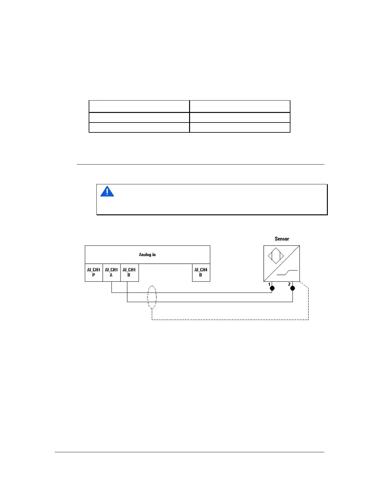
The figure below shows the screw terminal connections for the IMx-S.
Important - The sensor shield should be connected either to the sensor or to the
IMx-S unit depending on the cable and the sensor type. To avoid ground loops the
sensor shield should be connected only at one end.
Figure 3 - 1.
IMx-S Terminal Connection, Standard Accelerometer.
The IMx-S I/O board along with the corresponding analogue terminal list are shown
below.
 Loading...

