Unit Configuration
Relay Driver Outputs
3 - 6 SKF Multilog On-Line System IMx-S
User Manual – Revision S
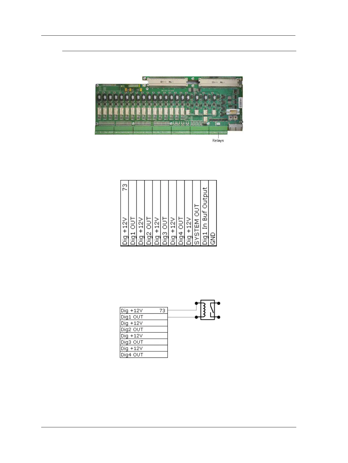
Relay Driver Outputs
The IMx-S I/O board has a total of five, relay driver outputs, the board along with the
corresponding relay terminal list are shown below.
Figure 3 - 5.
IMx-S I/O Board, Relays.
Table 3-9: Relay output connection list.
Software Controlled Relay Outputs
Each IMx-S 16 has four and IMx-S 32 has eight software controlled relay driver outputs
labelled as Dig1 OUT through Dig4 OUT (see terminal list above). These relay driver
outputs can be connected to relays as shown in the figure below.
Figure 3 - 6.
Relay Driver Output Connections.
Note that terminals Dig +12V always have the voltage +12 V, whereas terminals Dig1
OUT to Dig4 OUT are low side drivers known as open collectors.
 Loading...

