Unit Configuration
Dig1 Buffered Output
SKF Multilog On-Line System IMx-S 3 - 7
User Manual – Revision S
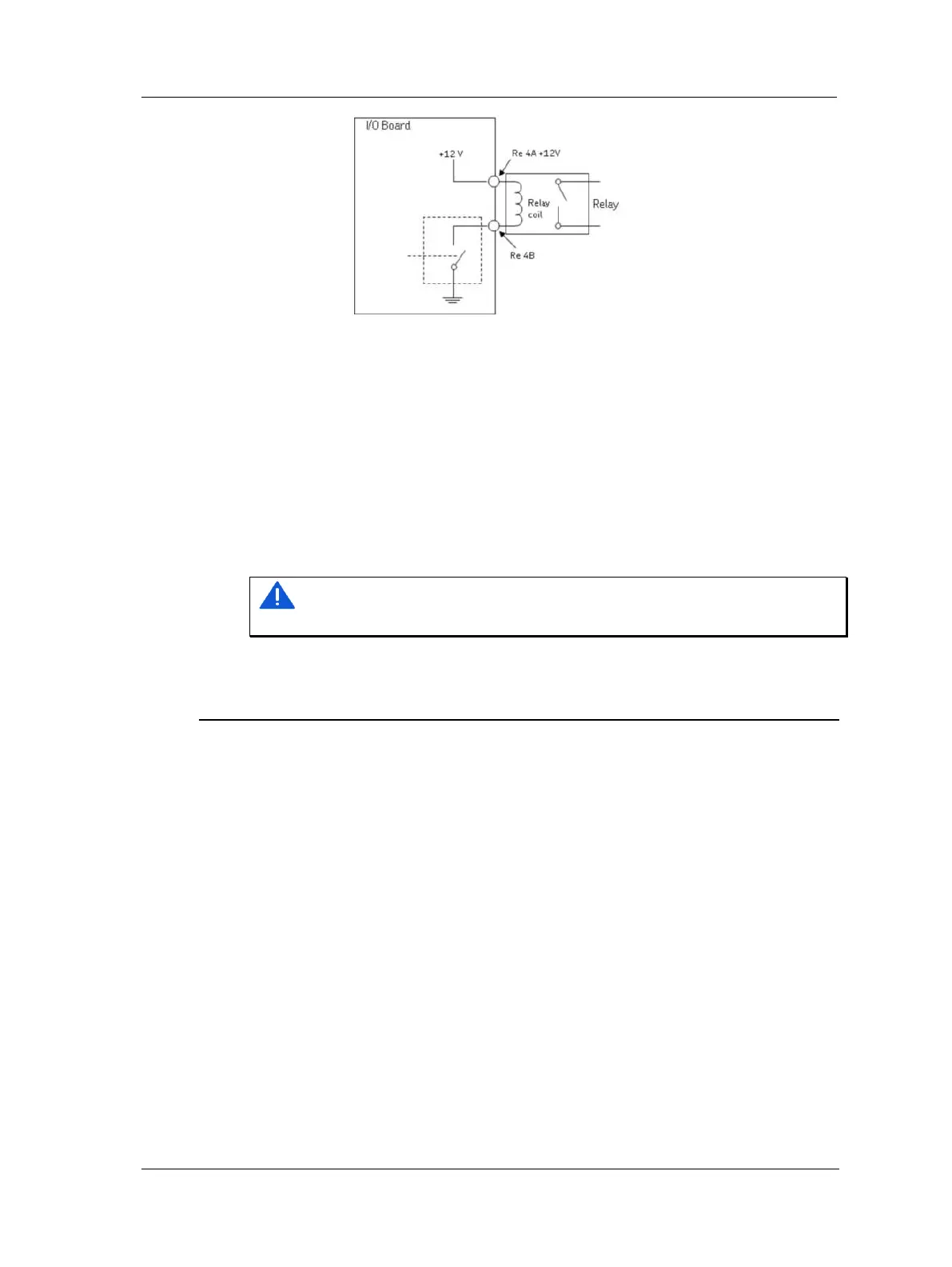
Figure 3 - 7.
Relay Open Collector Driver Showing Alarm Inactive.
System Relay Output
The relay driver output labelled SYSTEM OUT can be connected and used as an external
system alarm indicator.
This is a system fault relay drive that is hardware controlled and cannot be configured by
software.
The system relay driver output is always activated whilst the system is Ok, a "Fail-safe"
configuration.
Important - Total coil current for all five connected relays (Dig1 Out to Dig4 Out
and SYSTEM OUT) should not exceed 300 mA.
Dig1 Buffered Output
Each IMx-S 16 has one and the IMx-S 32 has two digital buffered outputs labelled as Dig1
In Buf Output (a buffered copy of the Dig1 input) as shown in Relay terminal list table,
above.
• Dig1 In Buf Output copies and buffers the signal from digital channel 1 labelled as
Dig1.
• This output is a low-side switch to GND. (The output does not provide any signal
power, just short to GND.)
• This output can be directly connected to a two-wire tachometer input in the other
IMx I/O board.
– Connect Dig1 In Buf Output to Tacho 2-wire input A and connect GND to Tacho
2-wire input B.
• Dig1 In Buf Output and GND are located in last two pins in the relay terminal block.
➢ On I/O board v1.24 and greater, those with a hole in front panel
for DIP21, the phase of the buffered output has been inverted.
This inverted buffered out will then have the same phase as the
input signal.
 Loading...

