15/22
Air – The output controls the air supply valve into
the feeder. The valve is switched on before
activation of the feeder. The time is set using
parameter A25 (Timer T11). When the feeder is
turned off, the air is turned off with a delay,
which is set using parameter A26 (Timer T12).
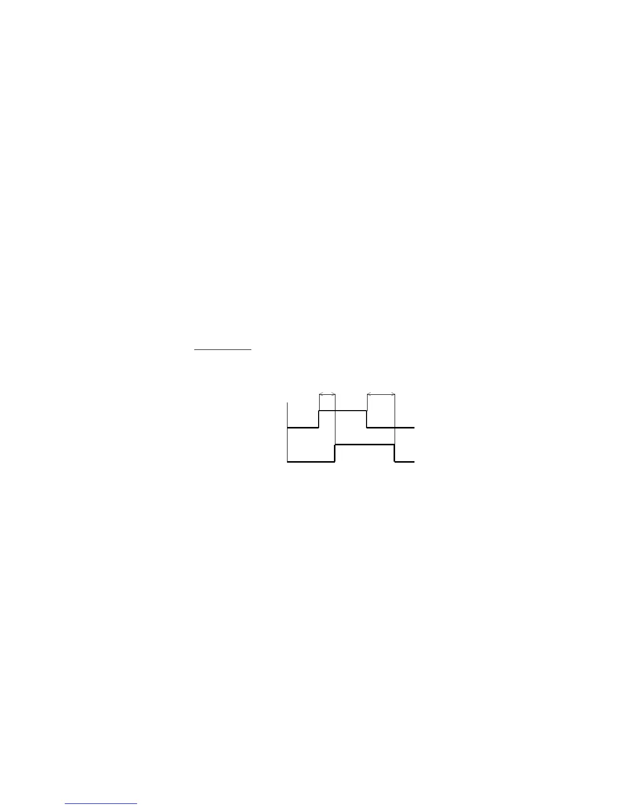
Ejector E1 (Fig. 9a) – The output is connected to the
valve controlling the ejector i.e. equipment
removing incorrectly oriented or redundant parts
from the route of the feeder. One of the inputs,
e.g. IN2, must be set to the ejector function
(Chapter 8.9.). The sensor is connected to the
input reading the parts. Use Timer T11 (parameter
A25) batch ON to set the timeout so that the
ejector does not respond to short impulses from
the sensor. Use Timer T12 (parameter A26) batch
OFF to change the ejection time.
Fig. 9a – activity of the ejector E1
Ejector E2 (Fig. 9b) – is similar to the ejector E1,
except that it uses three timers. Timer T11
(parameter A25) suppresses short impulses at the
input IN2. Timer T13 (parameter A27) determines
the delay between the signal IN2 and switching
output OUT. Timer T12 (parameter A26) determines
the length of switching output OUT. Ejector E2 is
good for example for detecting the stuck parts.
If parts are not passing under the sensor for
time T13 (parameter A27) the output OUT is
switched, which is connected to the valve that
controls air nozzles, which blow off stuck parts
from the feeder track.