38
5 Calibration
5.1 Calibration
Speed log Calibration
The electromagnetic speed log can be affected by magnetic materials near to
the sensor. It is therefore necessary to calibrate the sensor after it has been
installed. This is done by running the vessel back and forth over the same line on
the seabed several times, and entering the data from these calibration “trips” into
a calibration table. EMES60 uses the data in the calibration table to correct the
speeds measured by the speed log.
See section 5.10 for instructions on using the speed log calibration screen.
Speed log calibration is typically done during vessel sea trials.
A typical calibration sequence is as follows.
1. Choose a sea area to run the calibration trips. This needs to be in open
water, where the vessel can run between two defined points, one nautical
mile apart, at a range of speeds up to 75% of the vessel’s maximum speed.
The effects of wind and tidal currents should be minimized.
2. On the Speed log HMI, open the Speed log Calibration Screen.
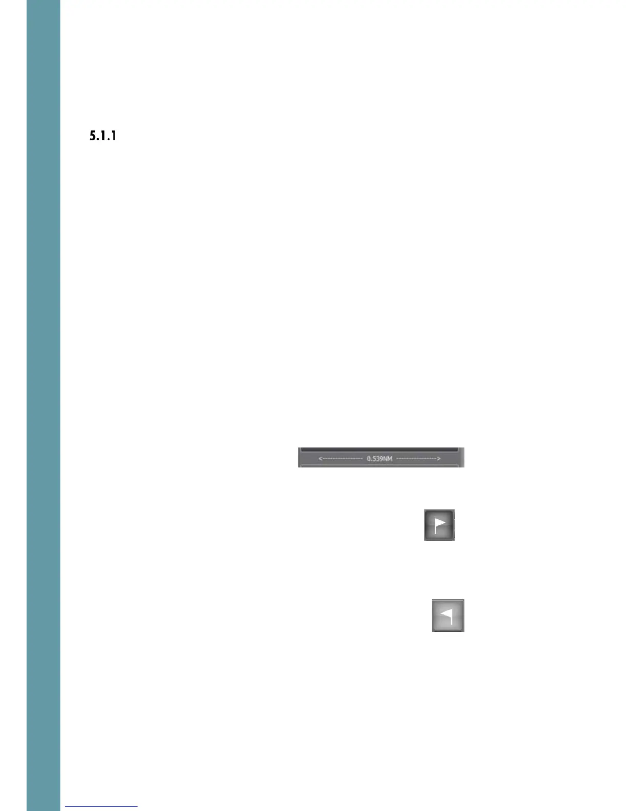
3. Select two points (which we will call point A and point B for the purpose of
this description). The points should be exactly 1 nautical mile apart (although
other separations can be selected if required: touch the distance indicator
at the top of the calibration screen to enter a new trip distance).
Most users enter these points on the ship’s
GPS plotter, although it is perfectly
possible to set up points using transits by aligning landmarks from a paper
chart, and measuring the distance from the chart.
4. Line up the vessel on a straight course from point A to point B,
travelling at approximately 25% of the ship’s maximum
speed. When point A is reached, press the trip start button
5. The progress along the first leg of the trip is shown as a progress bar above
the distance indicator. This progress is derived by integrating the speed log
speed, so it might not be exactly correct yet.
6. When the GPS plotter (or selected external navigation tool) indicates that
point B, the end of the calibration trip, has been reached,
touch the trip stop button.
7. The trip start button will now be flashing, waiting for the return leg
of the trip. Turn the ship around, head back down the same calibration line
at the same speed. Press the trip start button at point B, and the trip stop
button when point A is reached.
8. The software now gives the prompt message: “Set results in calibration
table?”
9. If you are confident that the results are good, select Ok, then use the drop-
down list to select a column number in the Calibration table. The