1616-920-03
8/28/2014
Rev: B
2
2.3 INSTALLATIONINSTRUCTIONS
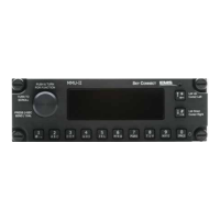
MMUIIisdesignedtobeinstalledinacockpitenvironmentsecuredtoDzusrails.A
suitablelocationshouldbefoundthatwillprovideenoughdepthinthepanelforthe
unitplustheconnectorswithamblebendradiusforthewiringharness.Failureto
dosomaydamagetheharnessandcauseamalfunctionofthesystem.
2.3.1 ELECTRICALINSTALLATION
Followtheinstallationdrawingintheappendixofthismanualasarecommended
methodtointerfacingtheMMUIItoaPOTSorRS‐232connection.Completelyread
thenotesprovided.
2.3.1.1POTSWIRING
Thisisa600Ohmtip/ringSubscriberLineInterfaceCircuit.
Theringingvoltageandcurrentisdependedonthenumberofringerloads.
ThePOTSspecusedcallsfor;
Theringingsignalisgeneratedbyswitchingthetransceiverintoringing
mode.Ringingvoltageofapproximately65Vrmsisappliedtoasingle
handset.DuringringingtheintegralDC/DCconverterautomatically
switchestoproduceabatteryvoltageof‐72V.Thiswillproducegreaterthan
40Vrmsintoaringloadof3.Theringingwaveformissetinternallytogive
thecorrectwaveformwith20Hzto25Hzringingfrequency.
Soringingisprovidedbyourtransceiverata20Hzcadenceandaring
voltageofgreaterthan40Vrmswith3ringerloads.
2.3.1.2InputsandOutputs
2.3.1.2.1 Outputs
Fourdiscretelampoutputsdesignedtoilluminatethelampsusedfor
IncomingMessageandthePhonelamps.Twonotusedatthistime.Phone
audiooutputat500Ωimpedancethatprovidesnominal5.0VACRMSaudioto
theheadsetsoraudiopanel.
2.3.1.2.2 Inputs
Microphoneaudioat150Ωimpedance.4VACthatconnectstotheheadsetsor
audiopanel.