SkyAzúl,EquipmentSolutionswww.skyazul.com301‐371‐6126
RemoteExternalComponents
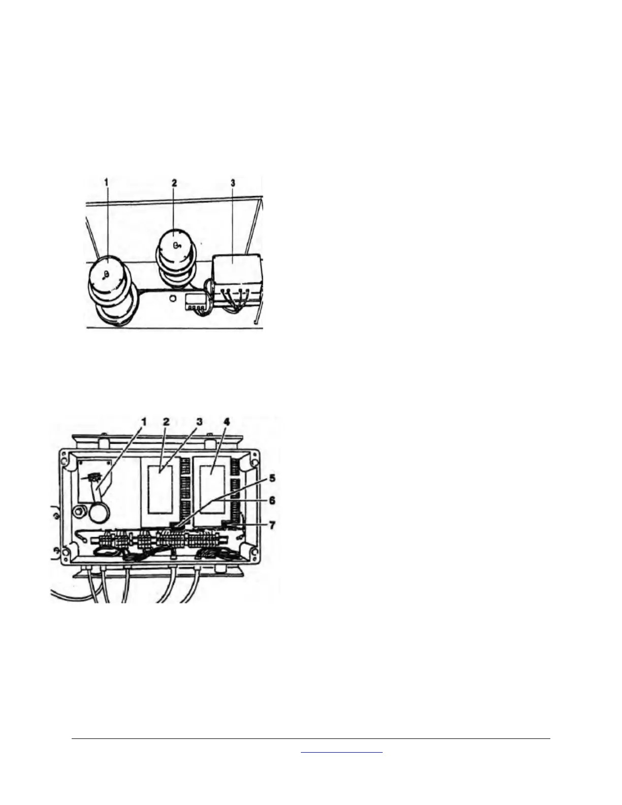
Below is the layout for the length & Angle transmitters on a GMK. 4070. Other models in the GMK range
will have more length reeling drums on the side of the boom and corresponding number of transmitters.
LMIBoom‐Lengthand‐‐Angle‐SensorsandTransmitters‐
1. Cable drum with potentiometer for length -
telescope sections III and IV
2. Cable drum with potentiometer for length -
telescope sections I and II
3. Boom unit with angle measurement and
data transmitter for angle and length
Boom‐Angle‐SensorandTransmittersBox‐
1. Angle potentiometer
2. Data transmitter (lower) - boom angle
3. Data transmitter (upper) – length telescope
sections 1/11
4. Data transmitter - length telescope sections
III/IV
5. Fuse (lower) (SU 3) 0.16 A M (medium time-
lag)
6. Fuse (upper) (SU 4) 0.16 A M (medium
time-lag) 1 per board
7. Fuse (SU 5) 0.16 A M (medium time-lag)